
Related Manuals for ELKHART BRASS Cobra EXM2 Series


Summary of Contents for ELKHART BRASS Cobra EXM2 Series
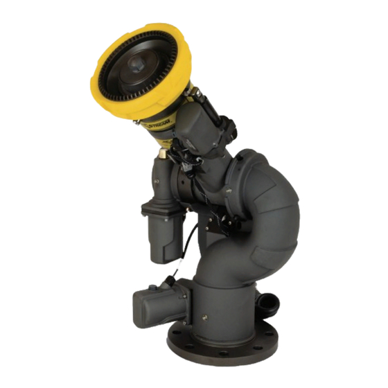
- Page 1 Installation, Operating, & Maintenance Instructions 98608000 REV-REL Cobra EXM2 Monitor Shown 1-574-295-8330 www.elkhartbrass.com...
-
Page 2: Table Of Contents
Contents PRODUCT SAFETY INFORMATION ..............4 SYSTEM INFORMATION: . - Page 3 MAINTENANCE INSTRUCTIONS............... 32 Preventive Maintenance .
-
Page 4: Product Safety Information
PRODUCT SAFETY INFORMATION • All personnel who may be expected to use this equipment must be thoroughly trained in its safe and proper use. • Before flowing water from this device, check that all personnel (fire service and civilian) are out of the stream path. -
Page 5: Exm2 Monitor Feature Callouts
EXM2 MONITOR FEATURE CALLOUTS X-Stream Series Master Stream Nozzle Double Race Bearings Manual Override Absolute Position Feedback Fully Vaned Cast Aluminum Waterway Sealed High-Torque Gearmotor Double Race Bearings 3" 150# Flange (other base options available) Cobra EXM2 Monitor Shown... -
Page 6: System Components
SYSTEM COMPONENTS MONITOR EXM2 Monitors The EXM2 monitors are specially designed to be compact providing a greatly reduced swing radius. Unique waterway swivel joints utilize stainless steel thrust rods, and needle roller thrust bearings, for unprecedented durability in a range of applications. -
Page 7: Control
CONTROL Joystick Controller – 7030X2 The Joystick Controller can be mounted inside the apparatus cab to control all monitor functions, including oscillation, stow and deploy. The monitor direction (both vertical and horizontal movement) is changed by moving the joystick in the desired direction of travel. The up-down and left-right motions can be operated simultaneously with pressure sensitive speed, moving the monitor faster or slower depending on how far the joystick is pushed and pulled. -
Page 8: Monitor & Valve Accessories
MONITOR & VALVE ACCESSORIES Position Feedback Display – 7051X2 All EXM2 monitors come with Absolute Position Feedback sensors. These sensors provide constant feedback to the monitors’ processor even when the monitor is moved via manual override. This information is then transmitted to the Position Feedback Display. -
Page 9: Recommended Electrical Requirements For The Exm2 Input Devices
Recommended electrical requirements for the EXM2 input devices • Power and Ground wire gauge and length: 18-20 AWG Cross link or equivalent 105°C 150V up to 150 ft. (45.7 m) • Maximum input controller amperage draw: 500mA • CAN wire type and shielding: Twisted shielded pair - 105°C 150V (Belden 9841 series or equivalent) •... -
Page 10: Installation Step 1: Mount And Wire All System Components
Installation Step 1: Mount and Wire All System Components • Before mounting the EXM2 monitor, ensure that space allows for monitor to be rotated and calibrated. Disconnect all electrical connections. • Mount the monitor onto base: Flange Size Bolt Size Torque 3(76.2)-150# 5/8-11 UNC grade 5... -
Page 11: Exm2 Motor Currents
EXM2 Motor Currents Sidewinder 7161UHPX2 – Heavy Duty Motors Motor (12 VDC) Left/Right Up/Down Run Current Current Trip Point 15 A 15 A Sidewinder 7100SDX2 – Standard Duty Motors Motor (12 VDC) Left/Right Up/Down Run Current 6 .5 A 6 .5 A Current Trip Point Sidewinder 7100HDX2 –... -
Page 12: Proximity Sensor For Extended Travel (Applies Only To Cobra Exm2)
Stow Output: The EXM2 monitor provides one electrical output to which an OEM can connect to in order to enable/disable truck operations based on whether an EXM2 monitor is stowed or not stowed. This could be used, for example, for a truck that has an aerial or other movable object that may hit the monitor if moved when the monitor is not stowed. -
Page 13: Exm2 Wiring Connections
Connecting an OEM supplied proximity sensor to the wire from position 4 will provide conditional extended travel functionality via a ground or open circuit (see Operating Instructions). Connecting the proximity sensor wire from position 4 to a ground will provide an always enabled extended travel. - Page 14 Harness E – EXM2 Extension harness (optional) Harness F – P/N 24196000 Splitter (optional) Harness G – P/N 24197000 CAN Termination Plug (optional) Harness H – P/N 37561000 Docking Station Pigtail included with EXM2 Hand Held pkg Harness J - P/N37551000 Gateway Pigtail included with EXM2 Hand Held pkg Harness K - P/N 37252000 Monitor CAN J1939 Pigtail Harness L - P/N 37571000 Input Controller CAN Pigtail...
-
Page 15: Panel Mount Controller
EXM2 Wiring Connections (Shown with all Elkhart Brass Provided harnessing) CAN Splitter CAN Splitter CAN Splitter Terminating Resister 7051X2 EXM2 Position 7010X2 EXM2 Panel Mount E14X/E16X EXM2 Monitor Feedback Module EXM2 Gateway Actuated Valve 7030X2 EXM2 Joystick Controller (Both Factory Set as Primary) -
Page 16: Handheld Controller, Gateway And Docking Station
Handheld Controller, Gateway and Docking Station Docking Station • Using the Docking Station template located at www.elkhartbrass.com, drill 6 #7(0.201" 5.1mm) drill holes as shown through the panel. • Mount the Docking Station with six (6) 10-24 screws using blue Loctite 242 or equivalent. -
Page 17: Joystick Controller
Joystick Controller • Using the Joystick Controller template located at www.elkhartbrass.com, drill all holes as shown through the panel. • Mount the Joystick Controller using 4 3/8" fasteners secured with blue Loctite 242 or equivalent. • Connect plug 2 to the appropriate CAN line. Joystick Plug Information •... -
Page 18: Position Feedback Display
Position Feedback Display • Using the Position Display template located at www.elkhartbrass.com, drill the two 11/64" holes as shown through the panel intended for mounting the display. • Mount the Position Feedback Display using two (2) 6-32 x ½" fasteners secured with blue Loctite 242 or equivalent. -
Page 19: Installation Step 2: Configure The Exm2 System
• Group number used for multiple monitors on system • Valve ID change for multiple valves • CAN address for special system of not using Elkhart Brass controls • Valve closure before stowing monitor need to be turned off If the system requires configuration, please refer to the EXM2 System Configuration Manual (P/N 98612001) for configuration instructions. -
Page 20: Installation Step 3: Calibrate The Exm2 System
Installation Step 3: Calibrate the EXM2 System NOTE: If calibration was completed during the previous step, skip step 3. After successfully installing the system, the system must be calibrated. Calibrating the EXM2 monitor’s horizontal and vertical rotation is a necessary step for EXM2 systems. If it was necessary to configure your system using Wi-Fi, calibration can also be done via the Wi-Fi interface. - Page 21 • Press and hold PRESET and then press and release either the LEFT or RIGHT button. (On the joystick, hold PRESET and move the stick to the right or left and release) The status LED on the monitor should blink then turn solid. •...
-
Page 22: Calibrate Valve
If an Elkhart Brass Unibody valve is being used in your system, calibrate it at this time by first placing the valve in a half open position using the manual override, and then pressing and holding the CLOSE and PRESET buttons on any controller until the valve calibration begins. -
Page 23: Operating Instructions
OPERATING INSTRUCTIONS A. Button / Joystick Operation • POWER – Turns Hand Held controller on and off. • OSC (OSCILLATE) – Used to set automatic motion of the monitor • STREAM – Moves the nozzle in order to flow a straight stream of water (See step I, Oscillation for directions) (Roll thumbwheel forward on the Joystick) - Page 24 • Monitor LEDs in Setup Mode Operation • When in Setup Mode, the status LED on the monitor control box will illuminate Magenta, and depending on motor speeds, the horizontal, vertical, and nozzle LEDs may or may not be lit. •...
- Page 25 • Blink meanings: • Green, Blue, or yellow blinking in a 1 blink continuous pattern indicates at least one of the following: • the monitor is moving • valve is moving • a button is being pushed on this panel mount. •...
-
Page 26: Setup Mode
• Blink meanings: • Green, Blue, or yellow blinking in a 1 blink continuous pattern indicates at least one of the following: • the monitor is moving • valve is moving • a button is being pushed on this panel mount. •... -
Page 27: Re-Calibrating Horizontal And Vertical Rotation
D. Re-calibrating Horizontal and Vertical Rotation Calibrating the EXM2 system’s horizontal and vertical rotation is a necessary step for EXM2 systems of all types. The calibration points serve as a starting point for all other motion limits and commands entered to the EXM2 system. If not properly calibrated, the system may not operate correctly. -
Page 28: Extended Travel (Applies Only To Cobra & Boa Exm2)
F. Extended Travel (Applies only to Cobra & Boa EXM2) The extended-travel-capable EXM2 monitor’s maximum vertical travel is dependent on the state of an additional input to position 4 of the 8-pin monitor power connector. This input allows the attachment of an OEM provided proximity sensor to trigger an open or grounded state of operation. -
Page 29: Stow Position
• Lower-Left Keep-Out Zone – The Left Keep-Out Zone will prevent the monitor from moving down and to the left into a specified zone (reference figure 1). • Put the EXM2 system into the Setup Mode (reference Part B of the Operating Instructions section) •... -
Page 30: Motor Speed
J. Motor Speed The speed of both the horizontal and vertical motors can be changed from something different than that set at the factory or during configuration of the EXM2 system. The monitor’s horizontal and vertical motors can be set to either Fast or Slow in one of four combinations. •... -
Page 31: Valve Operation
N. Valve Operation • OPEN – opens the valve. If the button is released, the valve will remain in the current position until another valve operation is performed. • In order to initiate auto-travel open, press and hold the OPEN button, then press and release the CLOSE button, then release the OPEN button. -
Page 32: Maintenance Instructions
MAINTENANCE INSTRUCTIONS Preventive Maintenance The complete monitor and control system should be inspected during each apparatus check. Careful inspection for damage to the monitor, valve or nozzle is especially important after use of the EXM2 monitor in emergency operations. • Operate all possible functions to ensure that each works normally •... -
Page 33: Troubleshooting Guide
Ensure the wires are completely plugged into the control module (Wiring diagram is located at www .elkhartbrass .com) . Order a replacement at Elkhart Brass 4 blinks continuous . Sensor indicates that monitor is moving in Check wiring diagram at the opposite direction of the expected . - Page 34 Check wires of the sensor for any damage . Ensure the wires are completely plugged into the control module (Wiring diagram is located at www .elkhartbrass .com) . Order a replacement at Elkhart Brass 4 blinks continuous . Sensor indicates that monitor is...
- Page 35 Ensure the wires are completely plugged into the control module (Wiring diagram is located at www .elkhartbrass .com) . Order a replacement at Elkhart Brass 4 blinks continuous . Sensor indicates that monitor is moving in the Check wiring diagram at opposite direction of the expected .
-
Page 36: Optional Accessory Specifications
OPTIONAL ACCESSORY SPECIFICATIONS Panel Mount Controller – 7010X2 12 or 24VDC Compatible Input power Electrical Load 0 .5 AMPS Fuse Rating 1 AMPS (12V) & 0 .5 AMPS (24V) 7 .54in(191 .5mm) x 3 .85in(97 .8mm) X 1 .48in(37 .6 mm) Controller Dimensions Controller Weight 1 . -
Page 37: Gateway - 7015X2Gw
Gateway – 7015X2GW Input power 12 or 24VDC Compatible Electrical Load 0 .5 AMPS 1 AMPS (12V) & 0 .5 AMPS (24V) Fuse Rating RF Power Output Meets FCC part 15 requirements for license free operation (See note on page 39) 6 .0in(152 .4mm)x4 .68in(118 .87mm)x4 .3in(109 .22mm) Transmitter Dimensions Transmitter Weight... - Page 38 . Modifications made to this equipment not expressly approved by Elkhart Brass Mfg . Co ., Inc ., could void the users authority to operate the equipment .
- Page 39 . Modifications made to this equipment not expressly approved by Elkhart Brass Mfg . Co ., Inc ., could void the users authority to operate the equipment .
- Page 40 Elkhart Brass Manufacturing Co ., Inc . 1302 W . Beardsley Avenue Elkhart, IN 46514 Tel . (574) 295-8330 Toll Free (800) 346-0250 Fax (574) 293-9914 www .elkhartbrass .com Email: eb .info@safefleet .net 98608000 REV-REL 09-18-20...
Need help?
Do you have a question about the Cobra EXM2 Series and is the answer not in the manual?
Questions and answers