Table of Contents
Advertisement
Quick Links
Advertisement
Table of Contents

Subscribe to Our Youtube Channel
Related Manuals for SIKA VA3K01

Summary of Contents for SIKA VA3K01
- Page 1 Operating manual (Translation) Operating manual ..........page 1 - 34 Panel mounting display Type VA3K01 Please keep this operating manual for future reference. If the device is resold, please provide the operating manual along with it.
-
Page 2: Table Of Contents
Switching the display during operation ..............19 Setting the presets ....................19 8.2.1 Setting via front keys .................... 19 8.2.2 Teach Function ...................... 19 8.2.3 Teach-In with tracking presets ................20 - 2 - © SIKA • Ba_VA3K01_en • 12/2019... - Page 3 VA3K01 Set Function ......................20 Default Parameters ....................20 8.4.1 Entry into the default setting ................20 8.4.2 Selecting the parameter sets ................20 8.4.3 Accepting the setting .................... 20 8.4.4 Parameter Set Table ..................... 21 Error Message ......................21 10 Connections .........................
-
Page 4: Preface
Preface VA3K01 2.1 Indended use 1 Preface The panel mounting display VA3K01 detects and measures pulses, times and frequen- Please read this instruction manual cies up to max. 60 kHz and offers a wide va- entirely and carefully before installa- riety of different operating modes. -
Page 5: Mounting In A Control Panel
VA3K01 Safety instructions and Warnings 2.2 Mounting in a control panel Mount the device away from heat Installation or maintenance work sources and avoid direct contact must only be carried out by quali- with corrosive liquids, hot steam fied personnel and in compliance... -
Page 6: Cleaning And Maintenance
Install the device as far away as possi- ble from noise-containing cables. Avoid routing signal or control cables parallel to power lines. - 6 - © SIKA • Ba_VA3K01_en • 12/2019... -
Page 7: Description
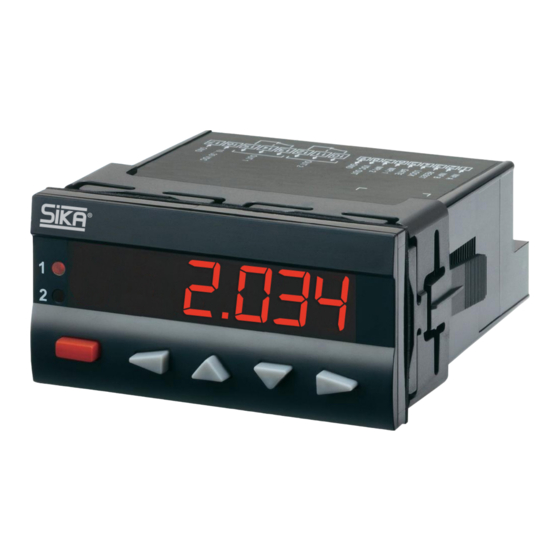
VA3K01 Description 3 Description 4 Display/Operating elements 6-digit 14-segment LED display, 14 mm Help Text display Preset counter with two relay outputs Preset entry via the front keys or via the Teach-In function Step or tracking preset ... -
Page 8: Inputs
The first parameter is dis- played with the current set- Relays with potential-free changeover con- ting flashing. tacts. Indicated by LED1 and 6.2 Active Outputs LED2 LED1 and LED2 indicate an active output. - 8 - © SIKA • Ba_VA3K01_en • 12/2019... -
Page 9: Selecting The Parameters
VA3K01 Programming Pressing the ENTER key 7.4 Selecting the parameters acknowledges this prompt The parameters are select- and terminates the pro- ed using either the RIGHT gramming; the modified key or the LEFT key. settings are saved in the EEPROM. -
Page 10: Pulse Counter
Quadrature with pulse quadrupling (x4) INP A: count input 0°. INP B: count input 90°. Each pulse edge of INP A and INP B will be counted. - 10 - © SIKA • Ba_VA3K01_en • 12/2019... - Page 11 VA3K01 Programming Batch counter counts the 7.8.3.2 Submenu for Output operations number of automatic repeti- tions of preset 2. Submenu for determining Output 1 active when Batch the operation of the outputs. counter ≥ preset 1. Manual reset sets both Output operation counters to zero.
- Page 12 § 7.9.5.5 . be accepted. 7.8.3.6 Preset 2 Division factor can be programmed from § 7.9.5.6 . 00.0001 to 99.9999 . A setting < 01.0000 will not be accepted. - 12 - © SIKA • Ba_VA3K01_en • 12/2019...
-
Page 13: Tacho/Frequency Meter
VA3K01 Programming User input 1 7.8.4 Tacho/Frequency meter User input 2 7.8.4.1 Submenu for the Signal and Con- trol inputs When the MPI input is acti- Submenu for programming vated the display is “frozen” the signal and control in- and remains “frozen” until puts. -
Page 14: Timer
§ 7.9.5.6 . tion. With AUTO: no output operations with automatic repeat. 7.8.5 Timer 7.8.5.1 Submenu for the Signal and Con- trol inputs Submenu for programming the signal and control in- puts. - 14 - © SIKA • Ba_VA3K01_en • 12/2019... - Page 15 VA3K01 Programming User input 1 Output 1 active when count status ≤ preset value 1. User input 2 Output 2 active when count status ≤ 0. When the MPI input is acti- Reset to preset 2. vated the display is “frozen”...
- Page 16 2 when main counter = zero. Total counter counts (sub from preset value 1) all count pulses from main counter. Decimal point setting Output 1 active when Total (determines the resolution) counter ≤ zero. - 16 - © SIKA • Ba_VA3K01_en • 12/2019...
- Page 17 VA3K01 Programming no decimal place Preset 1 ON/OFF 1 decimal place Preset 1 on. 0.00 2 decimal places 0.000 3 decimal places Preset 1 off and no function. Set value Output signal Set value can be pro- grammed from 000000 to ADD mode output operations: 999999.
- Page 18 SUB mode output operations: permanent signal at Output timed signal at Output 2, 2, becomes passive when becomes passive with nega- count ≥ Preset 2. tive direction and when count ≤ zero and subse- - 18 - © SIKA • Ba_VA3K01_en • 12/2019...
-
Page 19: Operation
VA3K01 Operation quently with positive direc- 8.2 Setting the presets tion and when count ≥ zero. 8.2.1 Setting via front keys Duration of timed signal of Using the UP key or the DOWN key, select Output 2 the preset to be changed, either PRES1 or PRES2 (... -
Page 20: Teach-In With Tracking Presets
2 sec. been permanently stored; these can be adapted as required. With each acknowledgment of the parameter sets, all parameters will be reset to the values listed in the table. - 20 - © SIKA • Ba_VA3K01_en • 12/2019... -
Page 21: Parameter Set Table
VA3K01 Error Message 8.4.4 Parameter Set Table 10 Connections P.SET1 P.SET2 P.SET3 HLP.TXT. SL.LANG. TACHO TACHO TACHO FUNCT INP.POL. FILTER TAC.INP LATCH LATCH LATCH MP.INP.1 TEACH TEACH TEACH MP.INP.2 PRG.PRE PRG.PRE PRG.PRE LOC.INP. TRAIL MODE 10.1 Signal and Control Inputs 00.1000... -
Page 22: Technical Data
HTL level Low: 0 ... 4 V control cables High: 12 ... 30 V Noise emission EN55011 Class B 4…30 V level Low: 0 ... 2V High: 3.5 … 30 V - 22 - © SIKA • Ba_VA3K01_en • 12/2019... -
Page 23: Scope Of Delivery
Core cross - section, max. 1.5 mm² typ. High 4.0 V AddAr AddTot SubAr SubTot 12 Scope of Delivery Trail AddBat SubBat Panel mounting display VA3K01. TrailAr Mounting clip. Cnt.Dir 9 kHz 2.5 kHz 2.2 kHz Operating manual. Up.Dn ; Up.Up 9 kHz 2.5 kHz 2.2 kHz... -
Page 24: Frequency Meter
Inp B: Count input sub Add: Display 0 --> Preset Sub: Display Preset --> 0 UP.UP Inp A: Count input 1 add Inp B: Count input 2 add Add: Display 0 --> Preset - 24 - © SIKA • Ba_VA3K01_en • 12/2019... - Page 25 VA3K01 Input modes: Pulse counting Function Diagram PNP: Count on rising edge NPN: Count on falling edge Note: No counting when GATE input is active QUAD A 90° B Inp A: Count input Count on one edge Inp B: Reverse direction Add: Display 0 -->...
-
Page 26: Input Modes: Timing
Sub: Display Preset --> 0 AUTO Inp A: no function Inp B: no function Control of the timing via RESET (manual or electrical) Add: Display 0 --> Preset Sub: Display Preset --> 0 - 26 - © SIKA • Ba_VA3K01_en • 12/2019... -
Page 27: Input Modes: Frequency Meter
VA3K01 Input modes: Frequency meter 16 Input modes: Frequency meter Function Diagram PNP: Count on rising edge NPN: Count on falling edge Inp A: Frequency input Inp B: no function A - B Inp A: Frequency input 1 Inp B: Frequency input 2... -
Page 28: Output Operations
Output operations VA3K01 17 Output operations Mode Diagram Mode Diagram Additionally in mode Only in mode ADD.AR SUB.AR ADD.BAT SUB.BAT ADD.TOT SUB.TOT - 28 - © SIKA • Ba_VA3K01_en • 12/2019... - Page 29 VA3K01 Output operations Mode Diagram TRAIL TR.AR Technical changes reserved - 29 -...
-
Page 30: Help Texts
TAC.INP. A%B INPUT MODE (A-B)/A IN % MP.INP._ LATCH FUNCTION MP-INPUT_ LATCH MP.INP._ TEACH FUNCTION MP-INPUT_ TEACH MP.INP._ SET FUNCTION MP-INPUT_ SET LOC.INP. PROG. LOCK PROGRAMMING LOC.INP. PRESET LOCK EDITING OF PRESETS - 30 - © SIKA • Ba_VA3K01_en • 12/2019... - Page 31 VA3K01 Help Texts Display Value Description LOC.INP. PRG.PRE. LOCK PROGRAMMING AND EDITING OF PRESETS MODE MAIN MENU OPERATION MODE MODE MODE ADDING MODE ADD.AR MODE ADDING WITH AUTOMATIC RESET MODE ADD.BAT MODE ADDING WITH AUTOMATIC RESET + BATCH COUNTER MODE ADD.TOT...
- Page 32 PR.OUT2 __--__--__ TIMED SIGNAL FORM IN BOTH DIRECTION AT OUTPUT 2 PR.OUT2 --_----_-- TIMED SIGNAL FORM IN BOTH DIRECTION AT OUTPUT 2 T.OUT 2 ACTIVE TIME FOR OUTPUT 2 END.PRG. NO REPEAT PROGRAMMING END.PRG. YES EXIT PROGRAMMING AND STORE DATAS - 32 - © SIKA • Ba_VA3K01_en • 12/2019...
-
Page 33: Dimensional Drawings
VA3K01 Dimensional Drawings 19 Dimensional Drawings +0.8 +0.6 +0.031 +0.024 Panel cut-out: 92 x 45 [3.662 x 1.722 Technical changes reserved - 33 -... - Page 34 VA3K01 For your notes - 34 - © SIKA • Ba_VA3K01_en • 12/2019...
- Page 35 VA3K01 For your notes Technical changes reserved - 35 -...
- Page 36 VA3K01 Mechanical measuring instruments Flow measuring instruments Electronic measuring- & calibration instruments SIKA Dr.Siebert & Kühn GmbH & Co. KG Struthweg 7–9 D-34260 Kaufungen Germany +49 (0)5605 803-0 +49 (0)5605 803-54 info@sika.net www.sika.net R60355.9468_1 - Englisch - 36 - ©...
Need help?
Do you have a question about the VA3K01 and is the answer not in the manual?
Questions and answers