
Related Manuals for Controls 58-E4800

Summary of Contents for Controls 58-E4800
- Page 1 58-E4800 Ultrasonic Pulse Velocity Tester MANUALE DI ISTRUZIONI INSTRUCTION MANUAL...
-
Page 3: Table Of Contents
Setting “Economy mode” ....................30 Switching off the instrument..................31 Use of the equipment with the flexible case and with the shoulder straps .....32 4. MAINTENANCE Preventive maintenance....................34 4.1.1 Checking the calibration ....................35 4.1.2 Replacing the batteries ....................36 58-E4800 Rev. 4 EN 21/05/2012... - Page 4 This instruction manual is an integral part of the machine and should be read before using the machine and be safely kept for future reference. CONTROLS reserves all rights of this manual, no part or whole can be copied without the written permission of CONTROLS .
-
Page 5: Introduction
The manual may not reflect changes to the product not impacting service operations. 58-E4800 is used to verify the quality of concrete. It allows the measurement of the transit time of an ultrasonic wave through concrete products such as beams, columns, walls, cubes, cylinders and other sample types and to determine the propagation time. -
Page 6: Icons Appearing In The Manual
This icon indicates a NOTE; please read thoroughly the items marked by this picture. This icon indicates a WARNING message; the items marked by this icon refer to the safety aspects of the operator and/or of the service engineer. 21/05/2012 58-E4800 Rev. 4 EN... -
Page 7: Manual Revision History
Added chapter: 27 January 2010 3.8 Use of the equipment with the flexible case and with the shoulder straps Rev. 3 Typing mistake 20 April 2011 Rev. 4 The wrong formula Cap. 3.3.8 21 May 2012 58-E4800 Rev. 4 EN 21/05/2012... -
Page 8: Symbols Used
Instruction Manual Symbols used In this manual and on the equipment itself, apart from the symbols indicated on the control panel, the following icons are also used: Symbol Description Dangerous voltage Conformity to the CE Directive 21/05/2012 58-E4800 Rev. 4 EN... -
Page 9: Intended Use And Improper Use
Instruction Manual Intended use and improper use The instrument 58-E4800 should only be used for the quality control of concrete. It allows the measurement of transit time of ultrasonic waves in concrete elements such as beams, columns, walls, cubes, cylinders and other sample types and determine the propagation time. -
Page 10: Safety Information
Safety information WARNING: Please read this chapter thoroughly. CONTROLS designs and builds its devices complying with the related safety requirements; furthermore it supplies all information necessary for correct use and the warnings related to use of the equipment. CONTROLS will not to be held responsible for: ... - Page 11 (at very low Energy). Always connect the probe head before switching on the instrument also ensuring that the cable is not damaged. Technical personnel Above listed areas Areas around compartments that contain electrical parts 58-E4800 Rev. 4 EN 21/05/2012...
- Page 12 WARNING: Failing to perform the recommended maintenance actions or maintenance performed by unauthorized people can void the warranty. CONTROLS will not be responsible for maintenance and service actions performed by unauthorized people. WARNING: Avoid pouring water, even accidentally, or other liquids into the device, as this could cause short circuits.
- Page 13 Refer to qualified service organization authorized by CONTROLS to carry out the service maintenance actions described in the chapter “Diagnostic and Troubleshooting”. CONTROLS has not to be held responsible for damages to the equipment and/or injuries to personnel in case the above is not strictly followed.
-
Page 14: Environmental Risks And Disposal
The correct disposal of this product and the subsequent treatment encourages the manufacture of products using re-cycled materials and limits the environmental impact of the product caused by improper disposal. Improper disposal of the product is subject to penalties as foreseen by the local regulations. 21/05/2012 58-E4800 Rev. 4 EN... -
Page 15: Ce Declaration
Manuale di Istruzioni Instruction Manual CE declaration This page shows a copy of the CE declaration. The original is supplied with the equipment as a separate document. 58-E4800 Rev. 4 EN 21/05/2012... -
Page 16: Description
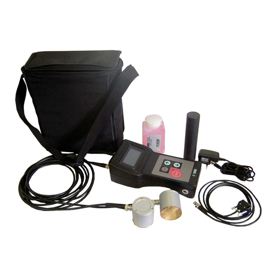
N°1 RS232 cable for PC connection N°1 Battery charger N°1 Sample bar N°1 ultrasonic pulse velocity tester, including 2 2400 mAh rechargeable batteries N°1 coupling agent (contact paste; (Glycerin 76%, ethylic alcohol 22%, excipients 2%) 21/05/2012 58-E4800 Rev. 4 EN... -
Page 17: Identification Plate
Manuale di Istruzioni Instruction Manual Identification plate The identification plate is located on the rear side of the equipment, near the power cable Fig. 2-2 58-E4800 Rev. 4 EN 21/05/2012... -
Page 18: Commands And Controls
Manuale di Istruzione Instruction Manual Commands and controls This chapter describes the commands and controls of the equipment. Fig. 2-3 Ref. Description Display ON/OFF key LED livello carica batteria Multifunction key Multifunction key Multifunction key Battery charger input and serial port output... -
Page 19: Technical Specifications
Manuale di Istruzioni Instruction Manual Technical specifications Main characteristics Product Strumento ad ultrasuoni CONTROLS Cernusco s/N (MI) Italy Manufacturer Product code 58-E4800 Single-phase line voltage 100 VAC/240 VAC +6%, -10% Frequency 50/60 Hz Max. current 90mA Method of power entry “Multirange”... -
Page 20: Use Of The Equipment
This chapter describes the operator’s interface and the execution of a test. WARNING: We recommend that the user carries out the checks listed in the chapter on maintenance before each work period. If any anomalies are noted, immediately inform an authorized technician in merit. 21/05/2012 58-E4800 Rev. 4 EN... -
Page 21: Recharging The Battery
Batteries should only be recharged with the ambient temperature between 10°C and 40°C. Power supply socket Fig. 3-1 During recharging the display shows: Fig. 3-2 NOTE: The instrument cannot be used whilst it is being recharged. 58-E4800 Rev. 4 EN 21/05/2012... - Page 22 It takes approximately 14 hours to completely recharge of the batteries. During recharging it is recommended that the battery charger is not disconnected/reconnected. The batteries can be recharged up to approximately 1000 times if recharged correctly. 21/05/2012 58-E4800 Rev. 4 EN...
-
Page 23: Preparation And Use
The value shown on the display is the transit time of the ultrasonic waves through the concrete from the transmitter to the receiver expressed in micro-seconds. Fig. 3-6 58-E4800 Rev. 4 EN 21/05/2012... - Page 24 To change the pulse rate, press the arrow down during the normal operation of the instrument. Fig. 3-7 NOTE: The set value is maintained even if the instrument is switched off. 21/05/2012 58-E4800 Rev. 4 EN...
- Page 25 (with gain high) the wave shape is square rather than a sine wave. In this case, reducing the gain to Low (L) a sine wave will be re-obtained. NOTE: Setting Low (L) in all other cases can result in incorrect readings. 58-E4800 Rev. 4 EN 21/05/2012...
-
Page 26: Interpretation Of Results
NOTE: The semi-direct transmission arrangement has a sensitivity intermediate between the other two arrangements and should only be used when the direct arrangement cannot be used. 21/05/2012 58-E4800 Rev. 4 EN... -
Page 27: Path Length And Pulse Velocity Measurement
The transmission times recorded should be plotted as points on a graph showing their relation to the distance separating the transducers. Pulse velocity determination by indirect (surface) transmission Fig. 3-10 58-E4800 Rev. 4 EN 21/05/2012... -
Page 28: Evaluation Of Homogeneity And Uniformity Of Concrete
3.3.6 Estimation of time for formwork striking and prestressing If some small doors are preset in the concrete moulds, it is possible to control the process of hardening in the concrete structure. 21/05/2012 58-E4800 Rev. 4 EN... -
Page 29: Estimation Of Dynamic Elastic Modulus
The related Static and Dynamic elastic module can be read on the vertical axis at the cross with "Static" and "Dynamic"curves. Static and Dynamic elastic module estimation from ultrasonic pulse Fig. 3-11 58-E4800 Rev. 4 EN 21/05/2012... -
Page 30: Depth Of Cracks
= crack depth (some measure unit of x) tc = transit time across the crack (unit msec) ts = transit time along the surface of the same type of concrete without defects (in msec) Fig. 3-12 21/05/2012 58-E4800 Rev. 4 EN... -
Page 31: Recommendation For The Proper Use Of The Ultrasonic Tester
Where the concrete presents irregular surfaces they should be ground to make them as smooth as possible and a suitable amount of concrete paste should be used to ensure the best contact possible. 58-E4800 Rev. 4 EN 21/05/2012... -
Page 32: Connection To An Oscilloscope
Refer to chapter 3.2 for more details on the selection of gain. NOTE: Setting Low (L) in all other cases can result in incorrect readings. 21/05/2012 58-E4800 Rev. 4 EN... -
Page 33: Connection To A Pc
RS232 port is excluded. To save the new setting keep the arrow up key pressed for 5 seconds. The instrument returns to the main screen. To exit without saving the new setting press STOP. Fig. 3-13 58-E4800 Rev. 4 EN 21/05/2012... -
Page 34: Setting "Economy Mode
(called ECONOMY MODE) to ON or OFF. This function allows longer autonomy of the batteries. The auto switch off will occur after 5 minutes from the last activation of any key of the instrument. Press the STOP key to exit. 21/05/2012 58-E4800 Rev. 4 EN... -
Page 35: Switching Off The Instrument
If the instrument is to be left off for a long time it recommended to remove the batteries (refer to chapter 4.1.2), otherwise damage could be caused to the instrument and the residual charge may be lost preventing the display of the Battery Low message on the display. 58-E4800 Rev. 4 EN 21/05/2012... -
Page 36: Use Of The Equipment With The Flexible Case And With The Shoulder Straps
The case allows also to fix a small flexible visor to protect the display against the rays of light. Flexible visor Fig. 3-15 The case also includes a support used when placing the instrument on a table. Support Fig. 3-16 21/05/2012 58-E4800 Rev. 4 EN... -
Page 37: Maintenance
WARNING: Failing to perform the recommended maintenance actions or maintenance performed by unauthorized people can void the warranty. CONTROLS will not be responsible for maintenance and service actions performed by unauthorized people. WARNING: Avoid pouring water, even accidentally, or other liquids into the device, as this could cause short circuits. -
Page 38: Preventive Maintenance
Before every working session connection cables Calibration checking (chapter 4.1.1) Operator 1 year and/or whenever the accuracy of results is in doubt General inspection Operator Weekly Replacement of batteries (chapter Qualified tecnica When necessary 4.1.2) personnel 21/05/2012 58-E4800 Rev. 4 EN... -
Page 39: Checking The Calibration
Press the STOP key to save the calibration. Fig. 4-1 To return to the main menu press STOP. The calibration will remain in the memory even when the instrument is switched off. 58-E4800 Rev. 4 EN 21/05/2012... -
Page 40: Replacing The Batteries
1. Use a screw driver to remove the screws of the back panel of the instrument; Fig. 4-2 2. When the instrument is open, take care not to damage the electrical components inside the instrument; Fig. 4-3 21/05/2012 58-E4800 Rev. 4 EN... - Page 41 To dispose of disused batteries refer to chapter 1.6. WARNING: Only use recharging batteries of the correct type (see chapter 6 for spare parts). Other types of batteries can explode causing damage to the person and material. 58-E4800 Rev. 4 EN 21/05/2012...
- Page 42 Refer to qualified service organization authorized by CONTROLS to carry out the service maintenance actions described in the chapter “Diagnostic and Troubleshooting”. CONTROLS has not to be held responsible for damages to the equipment and/or injuries to personnel in case the above is not strictly followed.
- Page 43 Check the connection of the flat display cable Check the correct connection of the probe heads Transit time not read Check the quality of the BNC cables Distance between probe heads too high Flat display Flat keyboard Fig. 5-1 58-E4800 Rev. 4 EN 21/05/2012...
- Page 44 Item description Quantity in the unit Orders for spare parts have to be addressed to CONTROLS representatives. When ordering spare parts, please provide code number, serial number, year of manufacture and any other useful information of the unit involved.
- Page 45 Sonda 54 Khz Head 54 Khz 58-E0048/5 Cavo coax. 3mt. Coax cable 3mt. 58-E0046/3 Gelatina Contact paste 58-E0046/30 Sonda 24 Khz Head 24 Khz 2 optional 58-E0046/33 Sonda 154 Khz Head 154 Khz 2 optional Fig. 6-1 58-E4800 Rev. 4 EN 21/05/2012...
- Page 46 Manuale di Istruzione Instruction Manual Notes: 21/05/2012 58-E4800 Rev. 4 EN...
- Page 47 Manuale di Istruzioni Instruction Manual Notes: 58-E4800 Rev. 4 EN 21/05/2012...
- Page 48 Manuale di Istruzione Instruction Manual Notes: 21/05/2012 58-E4800 Rev. 4 EN...
Need help?
Do you have a question about the 58-E4800 and is the answer not in the manual?
Questions and answers