Table of Contents
Advertisement
Advertisement
Table of Contents

Related Manuals for Penta KB Power KBMM-225

Summary of Contents for Penta KB Power KBMM-225
- Page 2 Installation and Operation Manual KBMM ™ Surface Mount Technology DECEL Solid State SCR DC Motor Speed Controls for Use with 1/100 – 3 HP, 90 and 180 Volt ACCEL Permanent Magnet and Shunt Wound DC Motors* AC Line Input: 115 and 208/230 Volts, 50/60 Hz This Manual Covers Models KBMM-125, 225, 225D PATENTED Ultra Fast Current Limit Circuit Prevents...
-
Page 3: Table Of Contents
TABLE OF CONTENTS Section Page Simplified Installation Instructions ............. 4 Safety Warning . - Page 4 TABLE OF CONTENTS (Continued) Figures Page Control Layout and General Connection Diagram ..........10 Mechanical Specifications .
-
Page 5: Simplified Installation Instructions
10 and as described in Section 6.1, on page 13. Model KBMM-125 is rated for 115 Volt AC line input only. Model KBMM-225 is rated for 230 Volt AC line input only. Model KBMM-225D is rated for 115 Volt AC line input (Jumper J1 in the “115” position) and 230 Volt AC line input (Jumper J1 in the “230”... - Page 6 1.5 AC line Fusing – It is required that an AC line fuse (supplied separately) be installed in the AC Line Fuse Holder, as shown in Figure 1, on page 10. Select the correct AC Line Fuse, as described in Section 8, on pages 20 and 21.
-
Page 7: Safety Warning
SAFETY WARNING – Please read carefully. Definition of Safety Warning Symbols: Electrical Hazard Warning Symbol – Failure to observe this warning could result in electrical shock or electrocution. Operational Hazard Warning Symbol – Failure to observe this warning could result in serious injury or death. -
Page 8: Introduction
Volt DC output and 3 HP for controls with 180 Volt DC output, by the use of KB’s Auxiliary Heat Sink . Models KBMM-225 and KBMM-225D also allow operation of 90 Volt DC motors when used on 208/230 Volt AC line input... - Page 9 Diagnostic LEDs – Power On (PWR ON) and Current Limit (CL). Model KBMM-125 operates on 115 Volt AC line input with 90 Volt DC motors. Model KBMM-225 operates on 230 Volt AC line input with 180 Volt DC motors or 90 Volt DC motors (step-down). - Jumper Selectable.
-
Page 10: Electrical Ratings
.75 (.6) 24.0 16.0 1.5 (1.1) 50, 100 0 - 180 12.0 1.5 (1.1) 24.0 16.0 3 (2.3) 100, 200 KBMM-225 9450 0 - 90* 12.0 .75 (.6) 24.0 16.0 1.5 (1.1) 0 - 90 12.0 .75 (.6) 24.0 16.0 1.5 (1.1) -
Page 11: Control Layout And General Connection Diagram
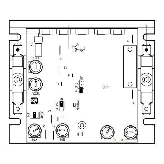
FIGURE 1 – CONTROL LAYOUT & GENERAL CONNECTION DIAGRAM (Model KBMM-225D Shown) (Note: Control is set for 208 / 230 VAC line input, 0 - 180 VDC output with armature feedback) Plug-In Horsepower Resistor® Supplied Separately Blue DECEL AC Line Fuse Armature Fuse Supplied Separately Supplied Separately... -
Page 12: Application Information
FIGURE 2 – MECHANICAL SPECIFICATIONS (Inches/mm) MAIN SPEED OPTIONAL AUXILIARY HEAT SINK 3.64 POTENTIOMETER 24.9 92.5 (SUPPLIED) 3.10 78.5 3/8" 1/2" 12.7 CONTROL MOUNTING "A" 6 SLOTS 5.63 1/4" ROUND MOUNTING "B" 7.00 SHAFT TAPPED 10-32 (3 PLACES) 4.30 3.00 3.11 3/8-32 76.2... -
Page 13: Mounting Instructions
4.3 Acceleration Start – The control contains an adjustable acceleration start feature which allows the motor to smoothly accelerate from zero speed to full speed over a time period of 0.2 - 10 seconds. The acceleration trimpot (ACCEL) is factory set for 2 seconds. 4.4 Limitation In Use –... -
Page 14: Minimum Supply Wire Size Requirements
See Section 7.1, on page 19. Model KBMM-125 operates on 115 Volt AC line input only. Model KBMM-225 operates on 208/230 Volt AC line input only. Model KBMM-225D operates on 115 Volt AC line input when Jumper J1 is set to the “115”... -
Page 15: Field Connection (Shunt Wound Motors Only)
(Armature Fuse) and the negative lead (-) to Terminal “A-”, as shown in Figure 1, on page 10. On Models KBMM-225 and KBMM-225D, be sure Jumper J2 is set to the corresponding motor voltage, as described in Section 7.2, on page 20. Be sure the correct Plug-In Horsepower Resistor® is installed, as described in Section 9, on page 21. -
Page 16: Remote Main Speed Potentiometer Connection
6.5 Remote Main Speed Potentiometer Connection – The control FIGURE 3 – REMOTE MAIN SPEED POTENTIOMETER CONNECTION is supplied with a Main Speed Potentiometer to control motor speed. Wire the low side of the potentiometer to Terminal “P1”. Terminal "P3" Wire the wiper of the potentiometer to Terminal “P2”. -
Page 17: Enable Switch Or Contact Wired To The Enable Connector
6.7 Enable Circuit Connection – The control can be started and stopped with an Enable Circuit (close to run, open to stop), as described below. WARNING! The Enable Circuit is never to be used as a Safety Disconnect since it is not fail-safe. -
Page 18: Enable Switch Or Contact Wired To The Main Speed Potentiometer
Volts DC). If the MIN FIGURE 6 – ENABLE SWITCH OR CONTACT WIRED TO THE MAIN SPEED POTENTIOMETER Trimpot is set to other than 0 Volts DC, the Terminal "P3" motor will run at that Terminal "P2" speed when the switch or contact is This jumper must Terminal "P1"... -
Page 19: Dc Tach-Generator Connection (7 Volts Per 1000 Rpm)
6.9 DC Tach-Generator Connection – A DC tach-generator FIGURE 8 – DC TACH-GENERATOR CONNECTION (7 VOLTS PER 1000 RPM) can be used for load regulation of 1% of the set speed. Note: Jumper J2 must be set to the “T” position for Terminal "T"... -
Page 20: Setting Selectable Jumpers
tach-generator. Connect one end of RT to Terminal FIGURE 10 – OTHER DC TACH-GENERATOR CONNECTION “T”, connect the other end of RT to the tach- generator positive lead (+), and connect the negative lead (-) of the tach-generator to Terminal “I2”. See Figure 10. -
Page 21: Ac Line And Armature Fusing
“180” position, on Models KBMM-225, 225D, for 180 115 Volt AC Line Input (Factory Setting) Volt DC motors. To set Models KBMM-225, 225D for step-down operation (208/230 Volt AC line input and 90 Volt DC output), set Jumper J2 to the “90” posi- tion). -
Page 22: Plug-In Horsepower Resistor
An AC Line Fuse (supplied separately) must be installed TABLE 5 – AC LINE & ARMATURE FUSE SELECTION in the AC line Fuse Holder and an Armature Fuse (sup- Recommended Fuse Rating 90 - 130 Volt 180 Volt (Amps) plied separately) must be installed in the Armature Fuse DC Motors DC Motors (HP) -
Page 23: Recommended High Voltage Dielectric Withstand Testing (Hi-Pot Testing)
TABLE 6 – PLUG-IN HORSEPOWER RESISTOR® SELECTION Plug-In Horsepower Resistor® 90 - 130 Volt DC Motors 180 Volt DC Motors (HP) (HP) Value (Ohms) Part No. 1/100 – 1/50 1/50 – 1/25 9833 1/50 – 1/30 1/25 – 1/15 9834 1/30 –... -
Page 24: Hi-Pot Test Setup
FIGURE 13 – HI-POT TEST SETUP High Voltage Dielectric Withstand Tester (Hi-Pot Tester) LEAKAGE AC KILOVOLTS 10mA RETURN TEST VOLTAGE Connect all Speed Control H. V. RESET terminals together ZERO Motor Speed Control AC Line input Motor Motor Wires Terminals Frame Connect Hi-Pot Tester Auxiliary Equipment... -
Page 25: 11 Trimpot Adjustments
10.2 The Hi-Pot Tester must have an automatic ramp-up to the test voltage and an automatic ramp-down to zero voltage. Note: If the Hi-Pot Tester does not have automatic ramping, then the hi-pot output must be manually increased to the test voltage and then manually reduced to zero. This procedure must be followed for each machine to be tested. -
Page 26: Deceleration Trimpot (Decel) Range
11.2 Deceleration Trimpot (DECEL) – The DECEL Trimpot controls the amount of FIGURE 15 DECEL TRIMPOT RANGE ramp-down time when the Main Speed Potentiometer is adjusted to a lower speed. The DECEL Trimpot has been factory set to 2 seconds, which is the amount of time it will take for the motor to decelerate from full speed to zero speed. -
Page 27: Current Limit Trimpot (Cl) Range
Warning! If possible, do not adjust trimpots with the main power applied. If adjustments are made with the main power applied, an insulated adjustment tool must be used and safety glasses must be worn. High voltage exists in this control. Electrocution can result if caution is not exer- cised. -
Page 28: Ir Compensation Trimpot (Ir) Range
wired in series with the motor armature). If using an AC ammeter wired in the AC line input, the factory Current Limit setting will read 0.75 times the full load rating of the motor. Do not exceed 2 times motor current rating (maximum clockwise position). Note: On cyclical loads, it may be normal for the CL LED to momentarily flash. -
Page 29: 12 Diagnostic Leds
Warning! If possible, do not adjust trimpots with the main power applied. If adjustments are made with the main power applied, an insulated adjustment tool must be used and safety glasses must be worn. High voltage exists in this control. Electrocution can result if caution is not exer- cised. -
Page 30: Typical Dynamic Brake Circuit Connection
WARNING! Do not disconnect and reconnect the motor armature with the AC line applied or cata- strophic failure will result. See Section 13.2. 13.2 Armature Switching and Dynamic FIGURE 20 – TYPICAL DYNAMIC BRAKE CIRCUIT CONNECTION Braking – If the armature is to be dis- connected and reconnected with the AC Speed Control N.O. -
Page 31: 14 Optional Accessories
13.3 Reversing and Dynamic Braking – The optional patented APRM® provides anti-plug “instant” reversing and solid state dynamic braking. The APRM® is built-in as standard on Models KBCC-R™ and KBPB™. Contact the Sales Department for more information. 14 OPTIONAL ACCESSORIES 14.1 Auxiliary Heat Sink (Part No. -
Page 32: Rfi Filter Selection
14.10 KBEP-240D Electronic Potentiometer (Part No. 9108) – Provides digital type control of motor speed. Replaces a standard rotary potentiometer with a set of customer supplied momentary push buttons or membrane switches. Operates on 115 or 230 Volt AC line input. 14.11 KBET-240D Electronic Tachometer (Part No. -
Page 33: Limited Warranty
LIMITED WARRANTY For a period of 5 years from the date of original purchase, KB Electronics, Inc. will repair or replace, without charge, devices which our examination proves to be defective in material or workmanship. This warranty is valid if the unit has not been tampered with by unauthorized persons, misused, abused, or improperly installed and has been used in accordance with the instructions and/or ratings supplied.
Need help?
Do you have a question about the KBMM-225 and is the answer not in the manual?
Questions and answers