Table of Contents
Advertisement
INSTALLATION AND OPERATING INSTRUCTIONS
MODEL SIMG
KB Part No. 8832 — Signal Isolator for KBMG-212D Regenerative Drive
Pending
!
See Safety Warning on Page 1
The information contained in this manual is intended to be accurate. However, the Manufacturer
retains the right to make changes in design which may not be included herein.
™
A COMPLETE LINE OF MOTOR DRIVES
© 2000 KB Electronics, Inc.
Advertisement
Table of Contents

Related Manuals for Penta KB Power SIMG

Summary of Contents for Penta KB Power SIMG
- Page 1 INSTALLATION AND OPERATING INSTRUCTIONS MODEL SIMG KB Part No. 8832 — Signal Isolator for KBMG-212D Regenerative Drive Pending See Safety Warning on Page 1 The information contained in this manual is intended to be accurate. However, the Manufacturer retains the right to make changes in design which may not be included herein.
-
Page 2: Table Of Contents
14. Removing The SIMG Finger Safe Cover Field Tab ......17... -
Page 3: Safety Warning
SAFETY WARNING! Please read carefully: Be sure to follow all instructions carefully. Fire and/or electrocution can result due to improper use of this product. This product should be installed and serviced by a qualified technician, electrician, or electrical maintenance person familiar with its operation and the hazard involved. Proper installation, which includes wiring, mounting in proper enclosure, fusing or other over cur- rent protection and grounding, can reduce the chance of electric shocks, fires, or explo- sion in this product or products used with this product, such as electric motors, switches,... -
Page 4: Introduction
All input connections (+15, -15, SIG, COM, and EN) are made via a barrier terminal block and are isolated from AC line and motor wiring. The SIMG is factory calibrated to accept a signal input voltage of -10V to +10V DC. OFFSET and MAX trimpots are provided in order to recalibrate the... -
Page 5: Control Layout
FIGURE 1 – CONTROL LAYOUT (Illustrates Factory Setting of Jumpers and Approximate Trimpot Settings) SIMG BIPOLAR SIGNAL ISOLATOR ENABLE 1.7A OFFSET CON2 A180 T1(-) TACH T2(+) - Page 6 FIGURE 2A – MECHANICAL SPECIFICATIONS (INCHES / mm) (Shown Mounted onto KBMG) 0.95 [24.21]...
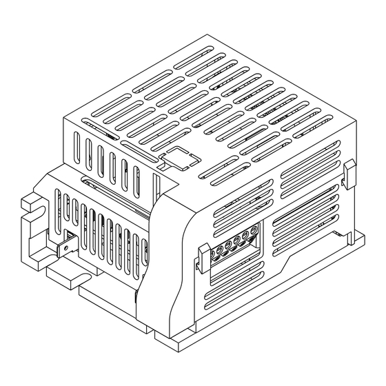
- Page 7 FIGURE 2B – MECHANICAL SPECIFICATIONS (INCHES / mm) (Shown Mounted onto KBMG) 3.80 [96.65] 0.48 [12.32] 2.50 2.67 [63.50] [67.92] 0.75 [19.05] 3.80 [96.52] 4.68 [118.99] RESP FACC RACC 0.19 [4.83] TYP...
-
Page 8: Installation Instructions
Ambient Operating Temperature Range (ºC) 0 – 50 — INSTALLATION INSTRUCTIONS: Mounting the SIMG onto the KBMG See figure 3 on page 7. Note: This figure is also supplied as a separate drawing. Warning! Make sure all power is disconnected from the KBMG before proceeding. -
Page 9: Kbmg/Simg Assembly Diagram
B. Removing Terminal Block FIGURE 3 – KBMG/SIMG ASSEMBLY DIAGRAM TB1 from the KBMG Remove terminal block TB1 from SIMG Finger-Safe Cover the KBMG by rocking it back and forth or using a screwdriver to gen- tly pry it off. See figure 5 on page... -
Page 10: Removing The Kbmg Finger-Safe Cover
Finger-Safe Cover E. Installing the SIMG onto the KBMG KBMG The terminal block located on the bottom of the SIMG plugs onto the six (6) header pins where removed from the KBMG. The two holes on the back of the SIMG snap onto the fin-... -
Page 11: Removing Terminal Block Tb1
FIGURE 6 – REMOVING THE KBMG FINGER-SAFE COVER PANEL KBMG FIGURE 7 – REMOVING THE KBMG FINGER-SAFE FIELD TAB KBMG Finger-Safe Cover KBMG Finger-Safe Cover Remove Tab (cut 3 places) to Access Field Terminals. Remove Panel (cut 7 places) to Install SIMG. -
Page 12: Connection Diagram
FIGURE 8 – CONNECTION DIAGRAM SIMG BIPOLAR SIGNAL ISOLATOR ENABLE LINE ARMATURE 1.7A OFFSET GROUND CON2 A180 T1(-) TACH T2(+) FIELD (SHUNT MOTORS ONLY) DC TACHOMETER GENERATOR... -
Page 13: Installing Field Connector
F. Wiring the SIMG to the KBMG See figure 8 on page 10. The SIMG is powered from the KBMG with a connector that is installed from the SIMG CON2 to the KBMG F+ and F- terminals. The yellow wire connects to the KBMG F+ terminal and the brown wire connects to the KBMG F- terminal. -
Page 14: Connections To The Simg
Use only the AC line for this purpose. Note: SIMG Enable jumper J1 must be installed, or a connection must be made between EN and COM terminals of SIMG TB1 in order for the KBMG to operate. TABLE 2 – TERMINAL BLOCK (TB1) WIRING INFORMATION Supply Wire Gauge (AWG –... -
Page 15: Main Speed Potentiometer Connections
Applying a negative (-) signal to SIG terminal, with respect to COM terminal, will operate the motor in the reverse direction. FIGURE 11 – MAIN SPEED POTENTIOMETER CONNECTIONS (KBMG Jumper J4 in 15V Position, SIMG Enable Jumper J1 Installed) Forward Reverse... -
Page 16: Resistor For Signal Following From Armature Voltage
FIGURE 12 – SIGNAL FOLLOWING FROM ARMATURE VOLTAGE Armature Voltage – Uses motor armature voltage as a signal input. If the signal input voltage applied to the SIMG is derived from a motor armature 1/4W Resistor Armature (See Table 3) - Page 17 0% (fully counterclockwise), the motor will operate at the minimum set speed (set by the OFFSET trimpot on the SIMG). When the potentiometer is set to 100% (fully clockwise) the motor will operate at full speed (set by the MAX trimpot on the SIMG).
-
Page 18: Enable Switch Connection
If a shunt wound motor is used, the motor field wires connect to F+ and F- terminals on the SIMG. To access these terminals, cut out the field tab of the SIMG finger-safe cover at three (3) places as shown in figure 14 on page 17. - Page 19 FIGURE 14 – REMOVING THE SIMG FINGER-SAFE COVER FIELD TAB SIMG Finger-Safe Cover Cut Out Tab (3 Places) to Access Field Terminals. (For Shunt Wound Motors Only.)
-
Page 20: Calibration Procedure
2. Monitor the KBMG output and adjust the OFFSET trimpot on the SIMG for the desired minimum setting. 3. Apply the maximum voltage input signal. 4. Monitor the KBMG output voltage and adjust the MAX trimpot on the SIMG for the desired maximum setting. B. Unidirectional Potentiometer Operation Calibration: See figure 11A, B or C on page 13. -
Page 21: Installing The Simg Finger-Safe Cover
(4) clips of the SIMG finger-safe cover into the four (4) slots of the KBMG finger-safe cover. Note: Ensure that the yellow and brown field wires (from CON2 of the SIMG to F+ and F- terminals of the KBMG) are within the shroud of the SIMG finger-safe cover. See fig-... - Page 22 – NOTES –...
- Page 23 – NOTES –...
-
Page 24: Vi. Limited Warranty
VI. LIMITED WARRANTY For a period of 18 months from the date of original purchase, KB Electronics, Inc. will repair or replace, without charge, devices which our examination proves to be defective in material or workmanship. This warranty is valid if the unit has not been tampered with by unauthorized persons, misused, abused, or improperly installed and has been used in accordance with the instructions and/or ratings supplied.
Need help?
Do you have a question about the SIMG and is the answer not in the manual?
Questions and answers