Table of Contents
Advertisement
Quick Links
DRA-CA-3300 Diffuse Reflectance Accessory
Introduction .............................................................................................................. 1
Unpacking and Inspection ....................................................................................... 3
Standard Components .................................................................................... 3
Optional Components .................................................................................... 3
Installation ................................................................................................................ 5
Optical Alignment of the Accessory ....................................................................... 8
Alignment Check ........................................................................................... 8
Aligning the Accessory Optics ...................................................................... 9
Diagnostic Scans .......................................................................................... 11
Operation ................................................................................................................ 14
Integrating Sphere ........................................................................................ 14
Optical Chamber .......................................................................................... 15
Loading the Sample Reflectance Port .......................................................... 15
Transmittance Sample Holder ...................................................................... 17
8°/Hemispherical Reflectance Factor Measurements .................................. 17
0°/Diffuse Reflectance Factor Measurements .............................................. 18
Large Sample Reflectance Measurements ................................................... 18
Transmittance Measurement Procedure ....................................................... 19
Theory of Operation ..................................................................................... 21
Double Beam Spectroscopy ......................................................................... 21
Reflectance Measurement of Non-Ideal Samples ........................................ 24
Zeroline Correction ...................................................................................... 26
Sources of Error ........................................................................................... 26
Optional Components ............................................................................................ 28
Center Mount Sample Holders .................................................................... 28
Powder Cell Holder ...................................................................................... 35
Transmittance Port Cuvette Holder .............................................................. 37
Maintenance ........................................................................................................... 39
Mirror Cleaning Procedure .......................................................................... 39
Spectralon Care Guide ................................................................................. 39
Troubleshooting the DRA-CA-3300 ............................................................ 40
Detector Replacement .................................................................................. 41
Appendix A Specifications .................................................................................... 42
Appendix B Typical Spectralon Reflectance Factors ......................................... 43
Appendix C Glossary ............................................................................................ 44
AQ-00275-000, Rev. 3
Advertisement
Table of Contents

Related Manuals for Labsphere DRA-CA-3300

Summary of Contents for Labsphere DRA-CA-3300
-
Page 1: Table Of Contents
Transmittance Port Cuvette Holder .............. 37 Maintenance ......................39 Mirror Cleaning Procedure ................39 Spectralon Care Guide ................. 39 Troubleshooting the DRA-CA-3300 ............40 Detector Replacement .................. 41 Appendix A Specifications ..................42 Appendix B Typical Spectralon Reflectance Factors ......... 43 Appendix C Glossary .................... -
Page 2: Introduction
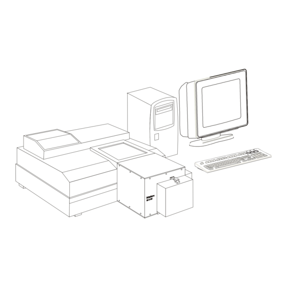
Figure 1. The DRA-CA-3300 replaces the existing sample compartment of the CARY 100 or CARY 300 spectrophotometers. Your DRA-CA-3300 is an integrating sphere accessory that replaces the sample compartment of your spectrophotometer. An integrating sphere is a hollow optical device, either constructed from or coated internally with a white diffusing material and fitted with the same detector as your spec- trophotometer. - Page 3 - you can still carry out the traditional transmittance and absorbance measurements as before. The DRA-CA-3300 reflectance accessory is designed for use with the CARY 100/300 UV-VIS Spectrophotometers. The sphere accessory is an optical bench composed of double beam transfer optics in combination with a six-inch (150 mm) diameter integrating sphere.
-
Page 4: Unpacking And Inspection
Unpacking and Inspection The DRA-CA-3300 accessory was thoroughly inspected and tested before shipping and should be ready to operate after completing the set-up instructions. All Labsphere instrumentation is pack- aged and shipped in reinforced shipping containers. Carefully check the components after unpack- ing for any damage that may have occurred during shipping. - Page 5 • Cuvette Holders: Sample or Reference Port(1 cm path length) • SRS-99-020 Calibrated Spectralon Reflectance Standard • Variable Angle Center-mount Sample Holders (VASH), Clip - used for analyzing thin films • Variable Angle Center-mount Sample Holders, Jaw - used for analyzing opaque, rigid solids •...
-
Page 6: Installation
Installation Your DRA-CA-3300 accessory comes already assembled - all you have to do is load the unit into the sample compartment of your spectrophotometer. WARNING: Do not touch the mirrors of the accessory. Fingerprints will induce optical scattering and may reduce reflectance or transmittance of these components at certain wavelengths. Only qualified service personnel should install reflectance accessories. - Page 7 Screw Pins NOTE: The DRA-CA-3300 is heavy and somewhat awkward to lift and maneuver. Installation may require two people and the use of a step-stool. Remove all packaging material from the optical chamber. Slide the accessory into the sample compartment area. If the accessory is already aligned, feed the accessory detector cable through the cutout on the base mount and plug the connector into the instrument.
- Page 8 cover to its closed position. Slide a sample wedge into the dovetailed plate at the sample reflectance port. The coated side should face the integrating sphere. Install the sample clamp over the dovetail. Reference or Sample Reflectance Port Reflectance Standard Dovetail 8 Wedge Sample Clamp...
-
Page 9: Optical Alignment Of The Accessory
The following procedure can be used to check optical alignment of the accessory. Note: The DRA-CA-3300 was aligned with mirror M3 in the reflectance measurement position. This mirror position is located closest to the integrating sphere. Any time mirror M3 is moved to the transmittance or center mount position, the accessory must be realigned. -
Page 10: Aligning The Accessory Optics
Click the Zero Order checkbox and select Apply. Open the lid to the accessory and remove the center mount plug. Slide the piece of translucent paper into the reflectance port sample holder just in front of the standard. Examine the location of the sample beams relative to the port. Check that the beam falls completely within the port surface area and does not over- fill the port. - Page 11 Sample Transmittance Port Reference Port Figure 5. Top view of the DRA-CA-3300 accessory. Place a piece of translucent paper or a white card in the beam path in front of M2. Turn the adjustment screws of mirror M1 until the beam is centered on M2.
-
Page 12: Diagnostic Scans
These scans were performed on your accessory with our instrument before we shipped the DRA-CA-3300 to you.You should perform these scans again on your instrument after installing the accessory to validate proper operation of the accessory. The scan results should be retained for future use. - Page 13 Save the scan. Sample Beam Energy Scan: Set up instrument parameters as listed on the Labsphere diagnostic scan reports in the quality assurance documentation. Change the instrument configuration to Single Rear beam mode from the Setup Dia- log Box.
- Page 14 Save the scan to a special directory on your computer. Reference Beam Energy Scan: Set up instrument parameters as listed on the Labsphere diagnostic scan reports in the quality assurance documentation. Change the instrument configuration to Single Front beam mode from the Setup Dia- log Box.
-
Page 15: Operation
Figure 6. Installing the transmittance sample holder and aperture plate on the integrating sphere. The DRA-CA-3300 integrating sphere features four beam ports, spread around the sphere at 90 ° intervals. The beam ports either admit the spectrophotometer instrument beam into the integrating... -
Page 16: Optical Chamber
The detector cable from the accessory is located inside the sphere compartment where it is perma- nently wired to a Labsphere designed socket. The connector at the opposite end of the cable plugs into the instrument detector connection in the bottom well of the sample compartment. When the cable is plugged in correctly, the instrument will recognize the presence of the DRA-CA-3300 accessory during initialization. - Page 17 reflectance port. To mount a sample at 8°, you must use the 8° wedge. Flip the clamp 180°, as shown in Figure 7, and slip the sample between the clamp and 8° wedge. 0 End 8 End Figure 7. The sample holder setup for 8°...
-
Page 18: Transmittance Sample Holder
The 8° reflectance measurement capability of the DRA-CA-3300 accessory is limited to the total hemi- spherical reflectance from a sample surface. The DRA-CA-3300 has no specular exclusion port - the dif- fuse and specular reflectance components cannot be separated. The following procedure should be used to measure total reflectance of a sample. -
Page 19: 0°/Diffuse Reflectance Factor Measurements
/Diffuse Reflectance Factor Measurements ° Although the DRA-CA-3300 integrating sphere does not have a specular exclusion port, the sam- ple beam entrance port can serve the same purpose when taking 0° incidence measurements. When the 0° wedge is in place, the specular component of reflection from the sample is redirected out of the sphere through the transmittance port. -
Page 20: Transmittance Measurement Procedure
Remove the enclosure assembly. With a 3/32" hex driver, loosen the two hex socket screws that hold the sample holder rail to the port frame. Remove the entire sample holder assembly. If necessary, loosen the two hex socket screws of the latch fixture and remove the latch fixture so that the exterior surface surrounding the port is free of all attach- ments. - Page 21 rail at the transmittance port. Set your instrument parameters as desired. Set the Y Mode parameter on the Setup Dialog Box of your WinUV application to %T. Perform an instrument baseline correction. Load the sample or sample cuvette at the transmittance port. Initiate the scan and record the measurement data.
-
Page 22: Theory Of Operation
When measuring the absorptance of a sample in the sample compartment, the detector signal of the spectrophotometer represents the portion of the sample beam that is not absorbed or scattered by the sample. When using the DRA-CA-3300 accessory, it is convenient to use the Kirchoff relationship: τ ρ... - Page 23 ρ κ ---------------- Eq. 2 ρ κ where: is the energy of the sample beam, is the energy of the reference beam, ρ is the reflectance factor of the sample at the sample reflectance port ρ is the reflectance factor of the reference port, and κ...
- Page 24 ρ κ ----------------- Eq. 4a ρ κ The instrument displays: ρ κ ρ κ ρ κ ----- - --------------------------------- - ----------- Eq. 4b ρ κ ρ κ ρ κ Assuming that the spatial distribution of energy reflected from this unknown sample is the same as that of the original standard, the efficiency factor (κ) will be the same for both materials: κ...
-
Page 25: Reflectance Measurement Of Non-Ideal Samples
4. Here it is assumed that the geometric scattering properties of the sample and the reference stan- dard are identical. Therefore, the efficiency factor for radiation reflected from each sample will be the same. If the geometric scattering properties of the sample differ greatly from those of the refer- ence, significant systematic errors may be introduced into the measurements. - Page 26 and R , respectively. SPEX Given the assumption that the geometric reflectance distribution of the test sample can be sepa- rated into two ideal components, one specular (S) and one perfectly Lambertian (D), and further assuming that the reference sample approximates a perfect lambertian distribution, so that its reflectance factor (ρ...
-
Page 27: Zeroline Correction
Zeroline Correction An integrating sphere is sensitive to small-angle scatter from the sample beam coupling optics. The scattered radiation strikes the wall of the integrating sphere near the reflectance sample port, creating a "halo" surrounding the port. This halo-effect causes a small error in the measurement of the reflectance factor that is most significant when measuring samples of very low reflectance. - Page 28 (BRDF) characteristics. The effects of wall radiance variations in Labsphere accessories have been reduced through inte- grating sphere design. The location of sample and reference ports on the sphere, as well as corre- sponding baffling, have been placed at equal angles from the optical axis of the detector.
-
Page 29: Optional Components
A center mount sample holder offers two distinct advantages over the external sphere sample hold- ers on the DRA-CA-3300. One advantage is the ability to vary the angle of incidence for reflec- tance and transmittance measurements. The other advantage is the ability to measure the transmittance and reflectance of a sample together. - Page 30 Labsphere has provided such small spot kits for a number of UV-VIS-NIR reflectance accessories. The DRA-CA-3300 utilizes a three position mirror to focus the sample beam at the transmittance port, sample reflectance port, or center mount posi- tions.
- Page 31 The Labsphere version of the Edwards fixture can accept a sample cross-section up to 38 mm x 44 mm and 10 mm thickness. In a double beam configuration, the Labsphere sample holder accom- modates incidence angles up to 15° without clipping the reference beam. For angles of incidence greater than 15°, you may need to resort to single beam operation.
- Page 32 Figure 13. The jaws easily will accommodate sample sizes up to 1.5" in length and width. This is the size of a Labsphere SRS-99-010 diffuse reflectance standard, however, the standard is mounted in a delrin casing with high absorption characteristics.
- Page 33 The reflectance standards at Labsphere, however, are calibrated at 8°. Before using a center mount sample holder, you will need to realign the transfer optics in the accessory.
- Page 34 Figure 14. The CMSH-3300-CUV loads the cuvette inside the integrating sphere. Labsphere cuvette center mount sample holders will accept any standard 12 mm square cuvette. A baffle located under the sample reduces measurement errors by preventing the detector from directly viewing the first strike on the sample.
- Page 35 Alignment Pins Compress Springs to Release Cuvette Retainer Clips Cuvette Figure 15. Loading a cuvette into the cuvette holder. Beam Alignment on the Cuvette Center Mount Sample Holder Before using a center mount sample holder, you will need to realign the transfer optics in the accessory.
-
Page 36: Powder Cell Holder
Transflectance or Absorbance Measurements Using the Cuvette Center Mount Sample Holder NOTE: Labsphere recommends using quartz cuvettes with four clear sides. Cuvettes with frosted or ribbed sides are not recommended. After completing the beam alignment procedure for the cuvette sample holder, follow this proce- dure to perform measurements. - Page 37 400-2500 nm wavelength range. Each sample holder comes as a set: one cell with a Spectralon insert for use as a reflectance standard, and an empty cell for loading your sample. The powder cells both feature a quartz window so the standard or sample can be mounted verti- cally.
-
Page 38: Transmittance Port Cuvette Holder
Spectralon inserts are available. You must specify the thickness desired and the diameter of the cavity. Gray Spectralon inserts are placed first into the PCH-Series Powder Cell Holder to partially fill the sample cavity so that less material is needed. Contact the Labsphere Technical Sales Department at (603) 927-4266 for further information. - Page 39 To measure transmittance using the cuvette sample holder, proceed as follows: Make sure the accessory optics are aligned to the transmittance port. Load an empty cuvette into the cuvette holder, or you can use a cuvette filled with your solvent. Set your instrument parameters.
-
Page 40: Maintenance
When not in use, the accessory should be stored in a controlled environment. Dust and moisture may adversely affect its performance. A cover to the optical chamber is provided to protect the DRA-CA-3300 optical bench from dust and exposure during long-term storage. Precautions: •... -
Page 41: Troubleshooting The Dra-Ca-3300
If either of these rings are pushed-in, the instrument will not initialize. If initialization problems persist after checking the items described above, contact the Labsphere Customer Service Department at (603) 927-4266 for assistance. -
Page 42: Detector Replacement
You can replace the detector by removing the accessory from the instrument and removing the panel underneath the accessory. The R928 plugs into a Labsphere designed socket. Disconnect the existing tube from the socket and install a new one in the same orientation as before. -
Page 43: Appendix A Specifications
Appendix A Specifications Accessory Specifications Total Weight 30 lbs Integrating Sphere Reflectance Material Spectralon Inner Dimensions 150 mm Reference Port 1" dia. Center Mount Port 60 mm dia. Reflectance Port 1" dia. Transmittance Port 25 mm Spectral Range 250-850 nm Sample Sizes Reflectance Unlimited... -
Page 44: Appendix B Typical Spectralon Reflectance Factors
Appendix B Typical Spectralon Reflectance Factors Wavelength Spectralon 8° Hemispherical Reflectance .973 .984 .991 .991 .992 .992 .991 .991 1000 .993 1100 .993 1200 .992 1300 .993 1400 .991 1500 .992 1600 .992 1700 .988 1800 .989 1900 .981 2000 .976 2100 .953... -
Page 45: Appendix C Glossary
Appendix C Glossary The following definitions are given in ASTM Standard E-284-90: diffuse reflection: reflection in which flux is scattered in many directions by diffusion at or below the surface. diffuse transmittance: ratio of the flux transmitted by a specimen to the incident flux, the trans- mitted flux being measured for all forward angles except the regular transmittance angle. - Page 46 as in a mirror. total transmittance: the ratio of the flux transmitted at all forward angles to the incident flux. transmittance: the ratio of transmitted flux to incident flux, under specified geometric and spec- tral conditions. transmittance factor: the ratio of the flux transmitted by a specimen and evaluated by a receiver to the flux passing through the same optical system and evaluated by the receiver when the speci- men is removed from the system.
Need help?
Do you have a question about the DRA-CA-3300 and is the answer not in the manual?
Questions and answers