Table of Contents
Advertisement
Introduction .................................................................................. 1
Unpacking and Inspection ........................................................... 2
Installation and Assembly ........................................................... 3
Installing the Accessory PC Board Kit ................................ 3
Accessory Alignment ........................................................... 6
Diagnostic Scans .................................................................. 8
System Description and Operation ........................................... 11
Integrating Sphere .............................................................. 11
Transfer Optics .................................................................. 12
Loading the Sample Holders ............................................. 12
Theory of Operation .......................................................... 13
Maintenance ............................................................................... 26
General Information ........................................................... 26
Mirror Cleaning Procedure ................................................ 26
Spectralon Cleaning Instructions ....................................... 26
Appendix A Specifications ........................................................ 27
Appendix B Typical Spectralon Reflectance Values ............... 28
Appendix C Substitution Error Sample Scans ....................... 29
Appendix D Reflectance Glossary ............................................ 31
Appendix E Recommended Reading ....................................... 33
AQ-00073-000, Rev. 7
RSA-PE-20
Advertisement
Table of Contents

Related Manuals for Labsphere RSA-PE-20

Summary of Contents for Labsphere RSA-PE-20
-
Page 1: Table Of Contents
Integrating Sphere .............. 11 Transfer Optics ..............12 Loading the Sample Holders ..........12 Theory of Operation ............13 Operating Procedures for the RSA-PE-20 Accessory ..21 Maintenance ................26 General Information ............26 Mirror Cleaning Procedure ..........26 Spectralon Cleaning Instructions ........26 Appendix A Specifications ............ -
Page 2: Introduction
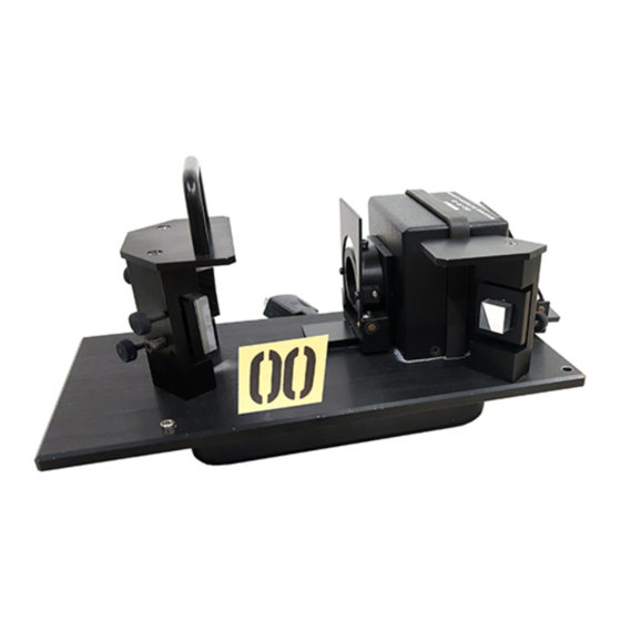
Lambda 25/35/45 series as well as the older models Lambda 2/12/14/20/40. The RSA-PE-20 accessory essentially is an optical bench, including transfer optics and an inte- grating sphere, that fits neatly into the sample compartment of the spectrometer instrument. An illustration of the accessory is provided in Figure 1. -
Page 3: Unpacking And Inspection
If your system was ordered directly from Labsphere, an instrument modification kit will accom- pany the accessory and the components listed below will be labeled by Labsphere part number. If your RSA-PE-20 was ordered through your PerkinElmer representative, the modification kit will be provided directly from PerkinElmer and installed by their qualified technician. -
Page 4: Installation And Assembly
Installation and Assembly In all cases, the RSA-PE-20 Accessory PC Board Kit installation should be accomplished by a qualified PerkinElmer technician. A technician is available through your local PerkinElmer rep- resentative. Once the accessory is installed, you can disconnect and reconnect the accessory as often as desired using the accessory installation procedure below. - Page 5 access door and open the top cover to gain access to the instrument. Loosen the two side plate mounting fasteners on the top, inside end of the plate. One of these screws fastens the cover leash - its removal will permit the spectrome- ter cover to fall back.
- Page 6 circuit board and lift the plate out of the instrument. Install the new side plate, Part No. EC-12201-000, into the instrument in the same orientation as the original plate. Reconnect the large ribbon cable into the same header connector located on the newly installed side plate.
-
Page 7: Installing The Accessory In Your Sample Compartment
Accessory Alignment The accessory was aligned precisely at the Labsphere factory before shipping and should be ready for use upon installation. Check the alignment of the accessory before using and, if neces- sary follow this procedure to adjust the optical alignment. - Page 8 Sample Beam Reflectance Port Figure 6. Optical setup of the RSA-PE-20 accessory. Make sure your UV Winlab software is configured for the sample beam at the front port. Place a piece of white translucent tissue paper in front of mirror M2. Adjust the thumbscrews on M1 so the beam is centered.
-
Page 9: Diagnostic Scans
These scans were performed on your accessory and our instrument before we shipped the RSA-PE-20 to you.You should perform these scans again on your instrument after installing the accessory to validate proper operation of the accessory. The scan results should be retained for future use. - Page 10 100% Baseline Scan This scan provides the direct comparison of a sample scan to the baseline at the same sphere configuration. The 100% baseline scan is used for general accessory troubleshooting purposes. Set up instrument parameters as listed in Table 2. Instrument Parameter Setting Lamps...
- Page 11 Set up instrument parameters as listed in Table 2. Leave the transmittance port empty and install a light trap over the sample reflec- tance port. Close the sample compartment door. Execute a sample scan and save the results. Time Drive Scan The time drive scan indicates the stability of the light source and the sphere detector.
-
Page 12: System Description And Operation
System Description and Operation The RSA-PE-20 accessory is specifically designed to measure the reflectance or transmittance of solids, liquids, powders, or other small objects that can fit in the transmittance or reflectance ports. Basic components of the accessory include the integrating sphere, transfer optics and detector preamplification module. -
Page 13: Transfer Optics
Appendix A. Transfer Optics The transfer optics of the RSA-PE-20 accessory direct the spectrometer sample beam to the transmittance port on the integrating sphere. The sample beam is the front beam in the accessory. -
Page 14: Theory Of Operation
When measuring the absorptance of a sample in the sample compartment, the detector signal of the spectrometer represents the portion of the sample beam that is not absorbed or scattered by the sample. When using the RSA-PE-20 accessory, it is convenient to use the Kirchoff relationship: AQ-00073-000, Rev. 7... - Page 15 where R = reflectance of the sample beam at the sample surface. During reflectance measurements, the reflected component of the sample beam is collected by the integrating sphere and detected by the sphere detector. The detector signal represents the part of the sample beam that is not transmitted and not absorbed by the sample substance.
- Page 16 The sphere efficiency factors (κ) for a given sample are a function of many variables including the spatial distribution of the energy reflected from the sample, the reflectance of the sphere wall, the geometry of the sphere (location of ports, baffles, etc.) and the efficiency of the detector itself.
- Page 17 ρ κ ρ κ ρ κ ----- - --------------------------------- - ----------- Eq. 4b ρ κ ρ κ ρ κ Assuming that the spatial distribution of energy reflected from this unknown sample is the same as that of the original standard, the efficiency factor (κ) will be the same for both materials: κ...
- Page 18 Although your PerkinElmer spectrometer may be a double beam instrument, the RSA-PE-20 is a single beam accessory such that combined operation is in dual beam spectrometer mode. The value of κ...
- Page 19 Although your spectrometer is a double instrument, the RSA-PE-20 is designed as a single beam accessory to accommodate the size of the instrument sample compartment. Since only the sample beam is subject to sphere configuration, your RSA-PE-20 measurements are subject to substitution error.
- Page 20 These values were determined with a PerkinElmer Lambda 2 double beam spectrom- eter and an RSA-PE-20 single beam accessory. Compare the charted L2 value and your mea- sured reflectance to the reflectance value under the column marked L19 immediately to its left.
- Page 21 Wavelength Gray14/L2 Gray14/L19 Gray16/L2 Gray16/L19 Gray18/L2 Gray18/L19 Gray20/L2 Gray20/L19 Gray22/L2 Gray22/L19 Gray23/L2 Gray23/L19 0.571 0.691 0.773 0.825 0.912 0.964 0.512 0.636 0.730 0.791 0.895 0.956 0.505 0.571 0.631 0.691 0.725 0.774 0.792 0.827 0.898 0.915 0.965 0.971 0.569 0.692 0.775 0.829 0.917 0.975...
-
Page 22: Operating Procedures For The Rsa-Pe-20 Accessory
Although calibrations using the 0° geome- try are available on a custom basis, the standard calibrations at Labsphere are performed at 8°. If your application requires NIST traceability, you should use a calibrated reflectance standard and the 8°... - Page 23 Choose your reflectance sample method from the UV Winlab software or manually set all instrument parameters as desired. Perform a background correction scan. Replace the reflectance standard at the sample reflectance port with your sample. Execute a sample scan and save the scan data. Multiply the values recorded in the resulting scan by the known spectral reflectance factor values of the reflectance standard to determine the actual reflectance of the sample.
- Page 24 Lambertian. The sample is measured in both total hemispherical (specular included) and diffuse (specular excluded) geometries, and the relative magnitude of the two components is estimated from the results. For the RSA-PE-20 accessory, the specular excluded geometry is at normal incidence where the specular component is rejected from the sphere back through the transmittance port.
- Page 25 ρ ) ρ ⁄ – Eq. 9 where S' represents the contribution of the specular component of the test sample to the apparent hemispherical reflectance factor of the sample. This quantity is analo- gous to the value M' given in Eq. 7 and its relation to the actual specular component of hemispherical reflectance (S) is described in Eq.
- Page 26 The following procedure can be used to measure total transmittance of a sample. Load a diffuse reflectance standard at the sample reflectance port. If you are scanning a liquid sample, load an empty cuvette into the cuvette holder, and load the entire cuvette holder assembly at the transmittance port. Otherwise, leave the transmittance port empty.
-
Page 27: Maintenance
When not in use, the accessory should be stored in the antistatic bag provided in a controlled environment. Dust and moisture may adversely affect its performance. Take the following pre- cautions when using your RSA-PE-20 accessory: • Never disconnect or connect the detector cable with the instrument powered •... -
Page 28: Appendix A Specifications
Appendix A Specifications Dimensions 10" x 4.5" x 5" 4 lbs Weight 190 - 1100 nm Spectral Range Integrating Sphere Spectralon Construction 50 mm (2") Sphere Diameter 5/8" Transmittance Port 5/8" Reflectance Port Hamamatsu S1227-66BQ Detector AQ-00073-000, Rev. 7... -
Page 29: Appendix B Typical Spectralon Reflectance Values
Appendix B Typical Spectralon Reflectance Values Wavelength Spectralon 8° Hemispherical Reflectance .973 .984 .991 .991 .992 .992 .991 .991 1000 .993 1100 .993 1200 .992 1300 .993 1400 .991 1500 .992 1600 .992 1700 .988 1800 .989 1900 .981 2000 .976 2100 .953... -
Page 30: Appendix C Substitution Error Sample Scans
Appendix C Substitution Error Sample Scans Figure 11. Spectral scan of green Spectralon, demonstrating the impact of substitution error. AQ-00073-000, Rev. 7... - Page 31 Figure 12. Spectral scans of blue and red Spectralon samples. AQ-00073-000, Rev. 7...
-
Page 32: Appendix D Reflectance Glossary
Appendix D Reflectance Glossary Diffuse Reflection. Reflection in which flux is scattered in many directions by diffusion at or below the surface. Diffuse Transmittance. Ratio of the flux transmitted by a specimen to the incident flux, the trans- mitted flux being measured for all forward angles except the regular transmittance angle. Diffusion. - Page 33 Specular Reflection. Reflection without diffusion, in accordance with the laws of optical reflec- tion, as in a mirror. Total Transmittance. The ratio of the flux transmitted at all forward angles to the incident flux. Transmittance. The ratio of transmitted flux to incident flux, under specified geometric and spec- tral conditions.
-
Page 34: Appendix E Recommended Reading
Hunter, R. S. and R. W. Harold,” The Measurement of Appearance”, Wiley Interscience, 1987. Kortum, G. “Reflectance Spectroscopy”, Springer-Verlag, 1969. Springsteen, A. W., "A Guide to Reflectance Spectroscopy," Labsphere Technical Guide , 1992. Springsteen, A. W., Leland, J. E., Ricker, T. M. " A Guide to Reflectance Materials and Coatings"...
Need help?
Do you have a question about the RSA-PE-20 and is the answer not in the manual?
Questions and answers