Sign In
Upload
Download
Table of Contents
Contents
Add to my manuals
Delete from my manuals
Share
URL of this page:
HTML Link:
Bookmark this page
Add
Manual will be automatically added to "My Manuals"
Print this page
×
Bookmark added
×
Added to my manuals
Manuals
Brands
Panasonic Manuals
Microwave Oven
NN-CF770M CPH
Service manual
Panasonic NN-CF770M CPH Service Manual
Hide thumbs
1
2
3
Table Of Contents
4
5
6
7
8
9
10
11
12
13
14
15
16
17
18
19
20
21
22
23
24
25
26
27
28
29
30
31
32
33
34
35
36
37
38
39
40
41
page
of
41
Go
/
41
Contents
Table of Contents
Troubleshooting
Bookmarks
Table of Contents
Table of Contents
Feature Chart
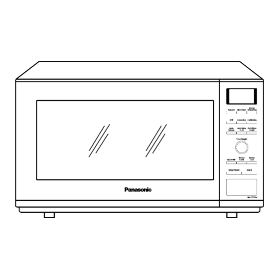
Control Panel
Schematic Diagram
Cph
Rph
Description of Operating Sequence
Variable Power Cooking Control
Inverter Power Supply Circuit
Auto Menu Cooking
Grill Cooking Control
Combination Cooking
Convection Cooking Control
Cautions to be Observed When Troubleshooting
Check the Grounding
Inverter Warnings
Part Replacement
When the 20A Fuse Is Blown Due to the Malfunction of the
Monitor Interlock Switch
Verification after Repair
Sharp Edges
Disassembly and Parts Replacement Procedure
Inverter Power Supply
Magnetron
Digital Programmer Circuit (D.P.C) & Membrane Sheet
Low Voltage Transformer And/Or Power Relays (RY1, RY2, RY4, RY5, RY6, RY7)
Fan Motor
Quartz Heater
Door Assembly
Stirrer Motor
Convection Fan Motor and Convection Heater
Component Test Procedure
Primary, Secondary Latch Switch Interlocks & Power Relay RY1
Monitor Interlock Switch
Magnetron
Inverter Power Supply (U)
Temperature Thermistor
Measurements and Adjustments
Adjustment of Primary Latch Switch, Secondary Latch Switch and Monitor Interlock Switch
Measurement of Microwave Output
Procedure for Measuring Microwave Energy Leakage
Equipment
Procedure for Measuring Radiation Leakage
Record Keeping and Notification after Measurement
At Least Once a Year, Have the Radiation Monitor Checked for Calibration by Its Manufacturer
Troubleshooting Guide
Troubleshooting) Oven Stops Operation During Cooking
Troubleshooting) Other Problems
Troubleshooting of Inverter Circuit (U) and Magnetron
Trouble Related to Digital Programmer Circuit
Simple Way of H.V. Inverter/Magnetron Troubleshooting
H.V.inverter Board Main Parts List (F606Y8X00Ap)
How to Check the Semiconductors Using an OHM Meter
Exploded View and Parts List
Exploded View
Parts List
Escutcheon Base Assembly
Door Assembly
Wiring Materials
Packing and Accessories
Digital Programmer Circuit
Schematic Diagram
Parts List
Advertisement
Quick Links
Download this manual
NN-CF770M
CPH (CANADA)
RPH (MEXICO & LATIN AMERICA)
© Panasonic Home Appliances Microwave Oven
(Shanghai) Co., Ltd. 2010.
ORDER NO.PHAMOS1007054C7
Microwave Oven
Table of
Contents
Previous
Page
Next
Page
1
2
3
4
5
Advertisement
Table of Contents
Troubleshooting
CAUTIONS TO BE OBSERVED WHEN TROUBLESHOOTING
10
TROUBLESHOOTING GUIDE
25
Troubleshooting) Oven stops operation during cooking
26
Troubleshooting) Other problems
27
Troubleshooting of inverter circuit (U) and magnetron
28
SIMPLE WAY OF H.V. INVERTER/MAGNETRON TROUBLESHOOTING
30
Need help?
Do you have a question about the NN-CF770M CPH and is the answer not in the manual?
Ask a question
Questions and answers
Related Manuals for Panasonic NN-CF770M CPH
Microwave Oven Panasonic Inverter NN-CF770M Operation Instruction And Cook Book
Microwave/grill/convection oven (70 pages)
Microwave Oven Panasonic Inverter NN-CF770M Operating Instructions Manual
1000 w convection microwave oven (38 pages)
Microwave Oven Panasonic NN-CF770M Operating Instruction And Cook Book
(31 pages)
Microwave Oven Panasonic NN-CF770M Operation Instruction And Cook Book
Microwave/grill/convection oven household use only (3 pages)
Panasonic NN-CF770M, NN-CF781S - Convection Microwave Oven Household Use Only Manual
(article)
Microwave Oven Panasonic NN-CF778S Cookery Book & Operating Instructions
(160 pages)
Microwave Oven Panasonic NN-CF778S Cookery Book & Operating Instructions
(166 pages)
Microwave Oven PANASONIC NN-CF760M Operating Instructions And Cookery Book
Microwave, grill & convection oven for models: nn-cf760m ; nn-cf750w (157 pages)
Microwave Oven Panasonic NN-CF771S Operating Instructions And Cookery Book
Microwave, grill & convection oven (163 pages)
Microwave Oven Panasonic NN-CF771S Operating Instructions Manual
(40 pages)
Microwave Oven Panasonic NN-CF760M Instruction Manual
(88 pages)
Microwave Oven Panasonic NN-CF874B Instruction Manual
(37 pages)
Microwave Oven Panasonic NN-CF771S Service Manual
(36 pages)
Microwave Oven Panasonic NN-CF873S Operating Instructions Manual
Microwave/grill/convection oven (46 pages)
Microwave Oven Panasonic NN-CF873S Operating Instructions Manual
Microwave, grill & convection oven (148 pages)
Microwave Oven Panasonic NN-CF876S Operating Instructions Manual
Convection (58 pages)
This manual is also suitable for:
Nn-cf770m
Nn-cf770m rph
Table of Contents
Save PDF
Print
Rename the bookmark
Delete bookmark?
Delete from my manuals?
Login
Sign In
OR
Sign in with Facebook
Sign in with Google
Upload manual
Upload from disk
Upload from URL


Need help?
Do you have a question about the NN-CF770M CPH and is the answer not in the manual?
Questions and answers