
Related Manuals for BZBGEAR BG-IPGEAR-4K

Summary of Contents for BZBGEAR BG-IPGEAR-4K
- Page 1 BG-IPGEAR-4K 4K@30Hz UHD HDMI 2.0 AV over IP Multicast System with Video Wall & PoE Support User Manual...
- Page 2 BZBGEAR IPGEAR-4K PRODUCT MANUAL · · Address: 830 National Drive #140, Sacramento, CA 95834, USA Tel: +1(888)499-9906 Email: support@bzbgear.com...
-
Page 3: Table Of Contents
Web Control Mapping Groups Video Wall Setup On Screen Display (OSD) Schedule (OSD) Setup History Account BZBGEAR Switcher Control Application Troubleshooting Tech Support Warranty Mission Statement Copyright · · Address: 830 National Drive #140, Sacramento, CA 95834, USA Tel: +1(888)499-9906... -
Page 4: Statement
● This product does not contain parts that can be maintained or repaired by users. Damage caused by dismantling the product without authorization from BZBGEAR is not covered under the warranty policy. ● Installation and use of this product must strictly comply with local electrical safety standards. -
Page 5: Introduction
PRODUCT MANUAL Introduction The BZBGEAR IPGEAR-4K AV over IP (AVoIP) system is composed of three components. The first is the BG-VOP-CB which is the controller for the system. Next, at least two BG-VOP-MT transceivers are needed which function as either transmitter or receiver. -
Page 6: Features
BZBGEAR IPGEAR-4K PRODUCT MANUAL Features ● Central Control for the IPGEAR-4K AV over IP system ● Monitors all system devices from one central system ● Optimized for 1 Gigabit networks ● Offers control via the web interface or mobile app (iOS) ●... -
Page 7: Vop-Cb Packing List
BZBGEAR IPGEAR-4K PRODUCT MANUAL BG-VOP-CB Packing List ● 1x BG-VOP-CB ● 1x Rack-mounting ear set ● 1x 5v DC power supply ● 1x User Manual BG- VOP-CB Specifications Technical Usage IPGEAR-4K System Controller Inputs 1 x 5VDC, 1 x RJ45, 4 x USB 2.0... -
Page 8: Vop-Mt Packing List
BZBGEAR IPGEAR-4K PRODUCT MANUAL BG-VOP-MT Packing List ● 1x BG-VOP-MT ● 1x IR receiver cable ● 1x IR blaster cable ● 1x User Manual BG-VOP-MT Specifications Technical HDMI compliance HDMI 2.0a HDCP compliance HDCP 2.2 Input Video Up to 4K2K@30 (4:4:4 8 bits) -
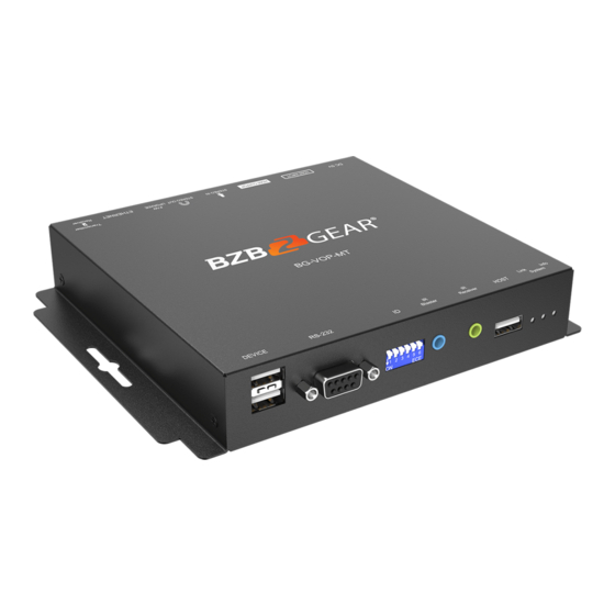
Page 9: Vop-Mt Panel Descriptions
BZBGEAR IPGEAR-4K PRODUCT MANUAL BG-VOP-MT Panel Descriptions 1. USB (USB 2.0 downstream port): Connect to USB flash drive or other USB devices (when device is configured as RX) 2. RS-232: Connect to PC with a DB-9 cable 3. Dip Switch: Video channel selection 4. -
Page 10: Ir Passthrough
BZBGEAR IPGEAR-4K PRODUCT MANUAL IR Passthrough [IR Extenders] IR Blaster IR Receiver [IR Sockets] IR BLASTER: Plug in the IR blaster to emit all IR command signals received from the IR receiver from the other end to control the devices corresponding to the IR signals. -
Page 11: System Requirements
BZBGEAR IPGEAR-4K PRODUCT MANUAL System Requirements For the BZBGEAR AVoIP system to function as intended the following items are needed: ● x2 BG-VOP-MT transceivers ● x1 BG-VOP-CB smart controller ● Managed network switch To ensure complete and reliable functionality any switch selected for an AVoIP system must meet the requirements below and support the following features: ●... - Page 12 BZBGEAR IPGEAR-4K PRODUCT MANUAL 2. Once the units are assigned as transmitter or receiver the ID of the unit will need to be set using the dipswitch panel. ● Transmitter needs to have an individual ID so they do not conflict in the control system.
- Page 13 BZBGEAR IPGEAR-4K PRODUCT MANUAL Pin1 Pin2 Pin3 Pin4 Pin5 Pin6 Pin1 Pin2 Pin3 Pin4 Pin5 Pin6 ↑ ↑ ↓ ↓ ↑ ↑ ↑ ↑ ↓ ↓ ↑ ↓ ↓ ↑ ↓ ↓ ↑ ↑ ↓ ↑ ↓ ↓ ↑ ↓...
- Page 14 BZBGEAR IPGEAR-4K PRODUCT MANUAL 3. Once the dipswitches are set, plug the transceivers into the PoE network switch to power them on. a. Connect sources to transmitters and displays to receivers using HDMI cables. b. When powered and connected to a display the receivers will display the following: 4.
-
Page 15: Web Control
BZBGEAR IPGEAR-4K PRODUCT MANUAL 6. Once the controller powers on you will see the following on the connected display: NOTE: If you do not see an image, power cycle the controller with all other cables connected and wait for the unit to reboot. -
Page 16: Mapping
BZBGEAR IPGEAR-4K PRODUCT MANUAL Mapping 1. Upon logging in you will be taken to the systems Mapping page. On this screen users can pair transmitters and receivers together, view and manage presets, as well as view grouped units. 3. The image previews on the Mapping page display useful information such as the group/pair ID in the top right, editable device name in the bottom left, and device IP address. - Page 17 BZBGEAR IPGEAR-4K PRODUCT MANUAL 4. To set a configuration as a preset click “Save as” dropdown and select the desired preset location. To recall a preset click the “Recall” drop down and select a preset that has been previously saved.
-
Page 18: Groups
BZBGEAR IPGEAR-4K PRODUCT MANUAL Groups Transmitters or receivers can be grouped together for easier identification and system management. To create or manage device groups select the “Group” tab from the menu on the left hand side of the web interface. - Page 19 BZBGEAR IPGEAR-4K PRODUCT MANUAL 2. Once the group is created, move to the next section on the screen and select the group name you just created from the “Group” dropdown menu. b. Click and drag devices from the bottom “Others” box to the “Group” box above.
-
Page 20: Video Wall Setup
5. The grouped device can now be filtered on the Mapping page using their respective drop down menus. Video Wall Setup The BG-IPGEAR-4K system is capable of forming multiple video walls simultaneously (maximum size 6x6 or 36 displays). To create a video wall select the “Video Wall” tab from the left hand menu. - Page 21 BZBGEAR IPGEAR-4K PRODUCT MANUAL 1. To create or edit a video wall select a Preset from the dropdown menu Users can edit the video wall “Preset Name” by typing in a desired name in the text field. 3. To edit the size of the video wall adjust the number of rows and columns up to a maximum of 6x6.
- Page 22 BZBGEAR IPGEAR-4K PRODUCT MANUAL 5. Click and drag receivers to their respective spot on the video wall to coordinate with the display position. 6. Once your receivers are placed in their position on the wall click “Save” to save the video wall layout.
- Page 23 BZBGEAR IPGEAR-4K PRODUCT MANUAL c. Use the sliders to adjust the bezel alignment of the selected screen. For vertical edges positive values shift the image up and negative values shift the image down. For horizontal edges positive values shift the image to the right and negative values shift the image to the left.
-
Page 24: On Screen Display (Osd)
BZBGEAR IPGEAR-4K PRODUCT MANUAL On Screen Display (OSD) The OSD menu allows users to brand video streams with a image or text overlay. 1. Users can upload their own.jpg or .png with a 1920*1080 resolution by clicking the upload button in the top right. -
Page 25: Schedule (Osd)
BZBGEAR IPGEAR-4K PRODUCT MANUAL Schedule (OSD) The Schedule (OSD) tab allows users to set a day and time for a message to automatically appear on a screen. · · Address: 830 National Drive #140, Sacramento, CA 95834, USA Tel: +1(888)499-9906... -
Page 26: Setup
Setup After connected BG-IPGEAR-4K transmitters and receivers are discovered by the control unit, the devices will be visible on the Setup tab under the Devices page. This page refreshes every 10 seconds automatically. - Page 27 BZBGEAR IPGEAR-4K PRODUCT MANUAL Receiver Setup From the Receiver Setup screen users can view device information and edit its settings. ● Name - Edits the device’s name. ● Streaming Video - Mutes the receiver’s video output. ● Scaling - Scales the output resolution to match a connected display.
- Page 28 BZBGEAR IPGEAR-4K PRODUCT MANUAL Transmitter Setup From the Transmitter Setup screen users can view device information and edit its settings. ● Name – Edits the device’s name. ● Group ID – Edits the device’s Group ID. It is recommended that users allow the system to automatically assign the Group ID.
-
Page 29: History
BZBGEAR IPGEAR-4K PRODUCT MANUAL History The History tab displays a list of recent system events for a specified date range (up to 500 entries). The event history can be cleared by clicking the red trash icon or exported by hitting the blue download button in the top right. -
Page 30: Account
BZBGEAR IPGEAR-4K PRODUCT MANUAL Account The Account page allows Admin users to change passwords, create other admin or standard user accounts, and set device permissions. Standard users do not have access to control or edit video walls or OSD messages. They can also be restricted to access/manage certain transmitters or receivers visible to the system by using the toggle switches in the Device Permissions section. -
Page 31: Bzbgear Switcher Control Application
BZBGEAR IPGEAR-4K PRODUCT MANUAL BZBGEAR Switcher Control Application A switcher control application developed by BZBGEAR specifically for our products is available to control the IPGEAR- K system. It is available for iOS, MAC, PC, and can be found on the controller product page on our website or via the Windows or Apple app stores. - Page 32 BZBGEAR IPGEAR-4K PRODUCT MANUAL From the “New Device” popup, select your device you wish to control from the model selection drop down. Type in a name for easy identification (optional). Next, type in the IP address of the device you wish to control. For the IPGEAR system the IP address can be found on the splash screen of the controller when it is connected to a display via HDMI.
- Page 33 BZBGEAR IPGEAR-4K PRODUCT MANUAL Mapping on the Switcher Control Application The control app for the IPGEAR system was designed to function much like the web interface for ease of use. On the main mapping page users can click and drag displays or sources to one another to pair devices together.
- Page 34 BZBGEAR IPGEAR-4K PRODUCT MANUAL Creating a Device Group using the Switcher Controller App For simpler management of larger systems displays and sources can be grouped together for easier identification. 1) From the options on the top of the Mapping page select the “Create Group”...
- Page 35 BZBGEAR IPGEAR-4K PRODUCT MANUAL 5) Click and drag the displays or sources to the group and they will be moved from the available list into the group folder. 6) Click on the group to view and manage the devices inside. Click “All Devices” to return to the main mapping page to view all groups and/or ungrouped devices.
- Page 36 BZBGEAR IPGEAR-4K PRODUCT MANUAL Creating a Video Wall using the Switcher Controller App 1) To create a video wall using the Switcher Control app click the “Create Video Wall” button at the top of the application. 2) On the Video Wall page click and drag displays to their respective position in the video wall.
- Page 37 BZBGEAR IPGEAR-4K PRODUCT MANUAL 4) Once a source is selected click the “Set Video Wall” button to create the video wall. 5) Use the “Set Bezel Correction” button at the top to adjust the image on the video wall to compensate for the border on all displays simultaneously.
- Page 38 BZBGEAR IPGEAR-4K PRODUCT MANUAL The video wall can now be viewed under the display section of the mapping page. To change the source of the video wall simply drag a source device to the Video Wall. Switcher Control Application Presets To save a mapping configuration as a preset select the “Save as...
-
Page 39: Troubleshooting
BZBGEAR IPGEAR-4K PRODUCT MANUAL Troubleshooting 1) No image/splash screen from control box: a) Ensure HDMI and ethernet cables are plugged in and power cycle the control box. 2) Transceiver(s) are not populating in the control software/web interface. a) Power cycle the transceivers by unplugging their ethernet cable and ensure the control box is plugged into the same network/VLAN as the transceivers. -
Page 40: Tech Support
BZBGEAR delivers quality products designed with users in mind. Copyright All the contents in this manual and its copyright are owned by BZBGEAR. No one is allowed to imitate, copy, or translate this manual without BZBGEAR’s permission. This manual contains no guarantee, standpoint expression or other implies in any form.
Need help?
Do you have a question about the BG-IPGEAR-4K and is the answer not in the manual?
Questions and answers