Table of Contents
Advertisement
Quick Links
Advertisement
Table of Contents

Related Manuals for FuturaSun Optor Tri 5K


Summary of Contents for FuturaSun Optor Tri 5K
- Page 1 INSTALLATION MANUAL HYBRID INVERTER Optor Tri 5K/6K/8K/10K/12K V 2023.06-MM - 1 -...
-
Page 2: Table Of Contents
CONTENTS INFORMATION REGARDING THIS MANUAL ..........................4 HOW TO USE THIS MANUAL ..............................4 1. SAFETY WARNINGS ................................4 2. DESCRIPTION OF THE PRODUCT ............................4 2.1 PRODUCT OVERVIEW ..............................5 2.2 PRODUCT DIMENSIONS ..............................6 2.3 PRODUCT FEATURES ..............................7 2.4 PRODUCT FEATURES .............................. - Page 3 5.3 ENERGY DATA PAGES AND CURVES ..........................31 5.4 MAIN SETUP MENU PAGE ............................32 5.5 BASIC SETTINGS ................................32 5.6 BATTERY SETTING ................................ 33 5.7 SYSTEM WORK MODE ..............................35 5.8 GRID SETTINGS ................................37 5.9 CEI 0-21 SELF-CHECK ..............................38 5.10 GEN PORT USE ................................
-
Page 4: Information Regarding This Manual
Contents may be periodically updated or revised as a result of product development. The information contained in this manual is subject to change without notice. For a copy of the latest version of this manual please contact info@futurasun.it 1. SAFETY WARNINGS This section contains important safety and operation instructions. -
Page 5: Product Overview
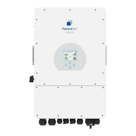
2.1 PRODUCT OVERVIEW 1 : INVERTER INDICATORS 7: RS 485 PORT FOR METER 13 : GRID CONNECTION 2 : LCD DISPLAY 8: BATTERY INPUT CONNECTORS 14: LOAD CONNECTION 3 : FUNCTION BUTTONS 9: FUNCTION TERMINALS 15: GENERATOR CONNECTION 4 : ON/OFF BUTTON 10: MODBUS PORT 16: WI-FI INTERFACE 5 : DC DISCONNECTOR... -
Page 6: Product Dimensions
2.2 PRODUCT DIMENSIONS - 6 -... -
Page 7: Product Features
2.3 PRODUCT FEATURES Self-consumption and feed into the grid Automatic restart Programmable power supply priority for the batteries or the grid Different operating modes: OnGrid, OffGrid and EPS Battery charging current and voltage selectable from display depending on application Display-selectable battery charging priority (grid, solar, generator) Compatible with grid or generator power supply Overload, overtemperature and short-circuit protection Smart battery charger design for optimised battery performance... -
Page 8: Installation
3. INSTALLATION 3.1 LIST OF COMPONENTS Check the components before the installation. Make sure that no components are damaged. The following components must be in the inverter package: 4 x M8*80 stainless steel 1 x Wall mounting bracket 1 x Hybrid Inverter bolts 1 x Temperature sensor 1 x Communication cable for... -
Page 9: Installation Instructions
3.2 INSTALLATION INSTRUCTIONS 3.2.1 INSTALLATION PRECAUTIONS The inverter is designed for outdoor use (IP65). The chosen installation site must comply with the following conditions: Avoid exposing the inverter to direct sunlight · Do not install the inverter in areas where flammable materials are present ·... -
Page 10: Installing The Inverter
3.2.3 INSTALLING THE INVERTER The inverter is heavy: be very careful when unpacking and handling it. To drill the fixing holes in the installation wall, choose the appropriate drill bit and drill 4 holes between 52 and 60 mm deep Use a hammer to insert the supplied expansion bolts into the holes. -
Page 11: Connecting The Batteries
3.3 CONNECTING THE BATTERIES To connect the batteries, use cables with dimensions as shown in the table below: Cable cross- Optor model Cable size Torque value (max) section (mm 5 kW 2 AWG 24.5 Nm 6 / 8 kW 1 AWG 24.5 Nm 10 / 12 kW 1/0 AWG... - Page 12 BMS CAN or BMS 485 port, depending on the type of communication required by the batteries. Only lithium batteries that are expressly compatible with the inverter can be used. In case of doubt, please contact the Technical Support Service of FuturaSun - 12 -...
-
Page 13: Specifications Of The Function Terminals
3.3.1 SPECIFICATIONS OF THE FUNCTION TERMINALS INVERTER PARALLEL B PARALLEL A MODBUS 1 2 3 4 5 6 7 8 1 2 3 4 5 6 7 8 RS 485 METER PARALLEL A: Inverter parallel communication port 1 (CAN interface) PARALLEL B: Inverter parallel communication port 2 (CAN interface) METER 485: RS485 port for communication... -
Page 14: Connection Of The Temperature Sensor For Lead/Acid Batteries
3.3.2 CONNECTION OF THE TEMPERATURE SENSOR FOR LEAD/ACID BATTERIES TEMPERATURE SENSOR If the inverter is connected to, and operated with, lithium batteries with corresponding BMS communication, installing and connecting the temperature sensor is not necessary. - 14 -... -
Page 15: Connection Of The Grid And The Backup Load
3.4 CONNECTION OF THE GRID AND THE BACKUP LOAD A circuit breaker with thermal-magnetic and differential protection between the inverter and the grid is required when connecting the inverter to the grid. Use the table below to choose the appropriate switch for the inverter being connected. Thermal-magnetic circuit Optor model Differential... - Page 16 LOAD GEN (GENERATOR) GRID LOAD GEN (GENERATOR) GRID - 16 -...
-
Page 17: Photovoltaic Field Connection
3.5 PHOTOVOLTAIC FIELD CONNECTION The inverter has 2 MPPTs and a physical input for the strings for each MPPT. PV1 = MPPT1 PV2 = MPPT2 Although the inverter is equipped with an on-board DC disconnector, it is strongly recommended that a DC switchboard is also installed, with, for each string: a pair of fuses of appropriate rating depending on the photovoltaic modules a Class II overvoltage arrester (SPD) -
Page 18: Photovoltaic Module Selection And Photovoltaic Generator Configuration
The calculated values must always be within the operating ranges of the inverter. Special configurations can be agreed with FuturaSun technicians Inverter failures caused by incorrect configuration of the photovoltaic field are not covered by the warranty. - Page 19 Open the plastic connector shell by unscrewing the lower cap Strip the string cables by approximately 7mm and run the cables inside the unscrewed caps. 7 mm 7 mm Insert the metal conductors of the solar cables into the appropriate holes in the metal parts of the connectors and crimp with a suitable crimping tool, checking that the cable is as tight as it should.
-
Page 20: Ct Connection
3.6 CT CONNECTION INVERTER GRID BLACK WIRE WHITE WIRE !!! THE ARROW OF THE CT MUST POINT TOWARDS THE INVERTER NO!!! BACKUP BACKUP LOAD LOAD Only the LINE conductor (L) - and not the NEUTRAL (N) - must pass through the CT NO!!! BACKUP BACKUP... -
Page 21: Connection With External Meter Chnt Dtsu 666
To check whether the CT has been positioned correctly and in the correct direction, switch on the inverter and keep the DC disconnector of the photovoltaic modules in the OFF position. Then switch on a domestic load of at least a few hundred watts. -
Page 22: Connection With External Meter Eastron Sdm630 Modbus V2
3.6.2 CONNECTION WITH EXTERNAL METER EASTRON SDM630 MODBUS V2 GRID INVERTER GRID EASTRON SDM630 MODBUS V2 N. PIN RJ45 RS485 PIN METER PIN 2 or 7 RS485A 12345678 1 or 8 RS485B 3.7 EARTH CONNECTION It is mandatory to earth the inverter housing using the appropriate earth connection found underneath the inverter, as shown in the image below. -
Page 23: Wi-Fi Plug Connection
3.8 WI-FI PLUG CONNECTION The WI-FI plug must be connected to the WI-FI/RS232 port as shown below. Refer to Chapter 8 for the plug configuration 3.9 DIAGRAM OF TYPICAL ONGRID CONNECTION PHASE NEUTRAL INVERTER BATTERY EARTH POWER CABLES(+ and -) SWITCHES SWITCH BATTERIES... - Page 24 3.10 DIAGRAM OF TYPICAL OFFGRID CONNECTION WITH GENERATOR PHASE NEUTRAL Coil RELAY SWITCH CN2: G-S (1-2): dry contact for generator start INVERTER GRID LOAD EARTH SWITCH SWITCH BATTERIES GEN start signal GENERATOR - 24 -...
-
Page 25: Diagram Of Single-Phase Connection With Parallel Inverter
3.11 DIAGRAM OF SINGLE-PHASE CONNECTION WITH PARALLEL INVERTER PHASE NEUTRAL INVERTER INVERTER 3 SLAVE EARTH INVERTER 2 SLAVE EARTH INVERTER 1 MASTER EARTH BATTERIES BMS CABLE ONLY TO MASTER The CT must only be connected to the master inverter GRID BACKUP Arrow towards LOADS... - Page 26 !!! MAXIMUM NUMBER OF INVERTERS THAT CAN BE CONNECTED IN PARALLEL, BOTH ONGRID AND OFFGRID = 10 UNITS To set the master inverter in a three-phase system, enter the "Advanced Function" menu of the inverter selected as master and tick the "Parallel" option and the "Master" options. In the "Modbus SN"...
-
Page 27: Operation
4 OPERATION 4.1 SWITCHING ON USING THE ON/OFF BUTTON Once the inverter and the batteries have been installed, the inverter can be switched on by simply pressing the ON/OFF button underneath the inverter. In a system without batteries, if the grid or the photovoltaic field are connected to the inverter and the button is in the OFF position, the display still lights up, showing the word OFF. -
Page 28: Lcd Display Icons
5 LCD DISPLAY ICONS 5.1 MAIN SCREEN The main screen of the LCD display shows the following general inverter information: 1) "ON" at the centre indicates that the system is working normally. The text turning to "comm./F01~F64” indicates that an operating error has been detected. The error message will be displayed underneath this icon (FXX Errors). The detailed error description can be viewed in the "SYSTEM ALARMS"... -
Page 29: Menu Structure
5.1.1 MENU STRUCTURE - 29 -... -
Page 30: Solar / Inverter / Load / Grid / Battery Information
5.2 SOLAR / INVERTER / LOAD / GRID / BATTERY INFORMATION SOLAR information page: ① Solar generation power ② Voltage, current, power for each MPPT. ③ Daily and total solar energy. Press "Energy" to access the power curve page INVERTER information page: ①... -
Page 31: Energy Data Pages And Curves
BATTERY information page. If lithium batteries are used, battery status information can be viewed in the BMS (Li-BMS) page 5.3 ENERGY DATA PAGES AND CURVES - 31 -... -
Page 32: Main Setup Menu Page
5.4 MAIN SETUP MENU PAGE 5.5 BASIC SETTINGS This page is used to set the date and time. TIME SYNC makes it possible to synchronise the date and time with the internet server. The inverter must be connected to the Internet BEEP can be used to enable/disable the button sound FACTORY RESET: All parameters are reset to the factory settings (PASSWORD 9999) -
Page 33: Battery Setting
5.6 BATTERY SETTING This menu can be used to configure the batteries used. LITHIUM: For lithium batteries NO BATT: If there are no batteries in the system USE BATT V: Use the battery voltage for all settings USE BATT %: Use the battery charge % (SOC) for all settings BATT CAPACITY: Enter the rated Ah battery capacity MAX A CHARGE/ DISCHARGE: Enter the maximum battery charge/discharge current (0-70A for 3K, 0-90A for 3.6K, 0-120A for... - Page 34 This page shows information on the use and the status of the generator. It shows voltage, frequency and power, as well as daily supplied and total energy. Settings for lithium batteries. LITHIUM MODE: It indicates the type of protocol and the port to use for the BMS.
-
Page 35: System Work Mode
5.7 SYSTEM WORK MODE Operating mode: SELLING FIRST: The inverter feeds all excess energy produced by the solar panels into the grid. If the "TIME OF USE" option is activated, battery energy can also be fed into and sold to the grid. The energy from the photovoltaic modules will be used to power the load and charge the battery, and only excess energy will be fed into the grid. - Page 36 SOLAR SELL: This option, which can be set either to ZERO EXPORT TO LOAD or ZERO EXPORT TO CT, allows any excess energy produced by the photovoltaic system to be fed into the grid. If it is not selected, the two programs indicated by default do not provide for such feeding into the grid.
-
Page 37: Grid Settings
5.8 GRID SETTINGS In this page, it will be necessary to select the correct regulation for the country of installation (GRID MODE), the grid frequency (GRID FREQUENCY), the phase sequence (PHASE TYPE) and the rated grid voltage (GRID LEVEL). Incorrect selection may cause damage to the inverter, not covered by the warranty. -
Page 38: Cei 0-21 Self-Check
V(W): It allows to set the active power of the inverter as a function of the detected grid voltage. It can be useful in the case of a network with high impedance. V(Q): It allows the reactive power of the inverter to be set as a function of the detected grid voltage. - Page 39 When asked for the password, enter "1234" and confirm During the self-check procedure, all LED indicators will be on and the alarm will sound. When "OK" appears at the side of every test, the self-check is complete. Press "ESC" to return to the previous menu. Now select "CEI 0-21 REPORT"...
-
Page 40: Gen Port Use
The page summarising the result of all tests performed will then be displayed. This can be photographed for the connection process. 5.10 GEN PORT USE The "GEN" port can be configured as input or output. When set as input, the incoming energy can only be used by the inverter to charge the batteries and not to directly power a load. -
Page 41: Advanced Function
5.11 ADVANCED FUNCTION SOALR ARC-FAULT ON: Option for USA SYSTEM SELFECHECK: Keep disabled. Only needed by the manufacturer. GEN PEAK SHAVING: Activate this option when the power required from the generator exceeds the rated power indicated in "RATED POWER". The inverter will supply power to the generator in order to avoid overloads. -
Page 42: Possible Operating Diagrams
6 POSSIBLE OPERATING DIAGRAMS DIAGRAM WITH INVERTER CONNECTED TO THE GRID AND BACKUP LOAD DIAGRAM WITH INVERTER CONNECTED TO THE GRID, BACKUP LOAD AND GENERATOR - 42 -... - Page 43 DIAGRAM WITH INVERTER CONNECTED TO THE GRID, WITH BACKUP LOAD AND SMART LOAD DIAGRAM WITH INVERTER CONNECTED TO THE GRID, BACKUP LOAD AND ONGRID INVERTER ON GEN PORT For each of the above diagrams, the primary source of energy is always photovoltaic. The second and third are the batteries or the grid, depending on the settings of the inverter.
-
Page 44: Error Messages
7 ERROR MESSAGES The inverter is designed for grid-connected operation and complies with the grid regulations for the countries for which it is certified as well as the safety and electromagnetic compatibility requirements. Before leaving the factory, the inverter undergoes several rigorous function tests. If, however, one of the error messages listed in table 7.1 should occur and the error should persist even after a restart of the inverter, please contact the support service with at least the following information Inverter serial number... -
Page 45: List Of Error Messages
7.1 LIST OF ERROR MESSAGES Error code Description Solutions PV input polarity Check the polarity of the strings inversion error If the fault persists, please contact the support service. The inverter fails to start due to a problem on the DC BUS of the photovoltaic or the batteries DC START error Try restarting the inverter. - Page 46 Error code Description Solutions The insulation resistance of the photovoltaic is too low DC insulation Check the insulation resistance of the photovoltaic field; impedance failure Check whether the PE cable of the inverter is connected to the earth; If the fault persists, please contact the support service. This error should clear itself after a while.
- Page 47 Error code Description Solutions Check that the input voltage from the photovoltaic modules is in the range permitted by the inverter and BUS bar DC voltage too Check that the battery voltage is not too high, and still within the high range allowed by the inverter;...
-
Page 48: Configuration Of The Wi-Fi Plug And Monitoring App
8. CONFIGURATION OF THE WI-FI PLUG AND MONITORING APP Once the Wi-FI plug has been installed and the inverter is switched on, the Wi-Fi plug can be configured. The plug has three status LEDs; their meanings are summarised in the table below: REFERENCE STATUS DESCRIPTION 1. - Page 49 The plug is equipped with a reset button Button Pressure Duration Description LED status All LEDs switch off 5 seconds Plug Restart immediately All LEDs switch off after 4 seconds. When the plug is 10 seconds Plug reset ready, the LED flashes every 100 ms Download the SOLARMAN app to your smartphone and start it.
- Page 50 Press "ADD A DEVICE” to add the Wi-Fi PLUG The PLUG can be entered manually or by scanning the barcode using the icon on the far right in the text box. After adding the logger, it will be necessary to configure the WI-FI communication. Go to "PLANT DETAILS", "DEVICE LIST", find the serial number of the logger entered and press its "DEVICE NETWORKING"...
- Page 51 Select the WI-FI network, enter the password and press "START TO CONFIGURE” Now you need to connect your smartphone to the WI-FI generated by the PLUG. To do this, on the next screen press "GO TO CONNECT" and then select the network called “AP_” followed by the serial number of the PLUG - 51 -...
- Page 52 Wait for the automatic configuration process and then press "DONE" The system data will be displayed approximately 10 minutes after start-up. If the configuration fails, please check: 1) That your WI-FI is working correctly 2) That the PLUG is working correctly by checking its LEDs 3) That the router does not have blacklists in which the PLUG connection may have been included 4) Delete all special characters from the network name and password 5) Boost the WI-FI signal of the router to the PLUG...
-
Page 53: Technical Data
9. TECHNICAL DATA OPTOR TRI5K OPTOR TRI6K OPTOR TRI8K OPTOR TRI10K OPTOR TRI12K Model Battery input data Type of batteries supported Lead-acid or Lithium Battery voltage range (V) 40-60V Max. Charge current (A) 120 A 150 A 190 A 210 A 240 A Max. - Page 54 10. APPENDIX I BMS RJ45 port PIN specifications BMS PORT RS485 Pin RS485_B RS485_A CAN-H CAN-L GND_485 RS485_A RS485_B METER-485 RJ45 port PIN specifications RS485 METER PORT RS485 Pin METER-RS485_B METER-RS485_A COM-GND COM-GND METER-RS485_A METER-RS485_B MODBUS RTU RJ45 port PIN specifications RS485 Pin MODBUS PORT RS485_B...
- Page 55 RS232 port PIN specifications WIFI/RS232 D-GND 12Vdc 11. APPENDIX II CT dimensions in mm. The connecting cable has a length of 4 metres - 55 -...
- Page 56 For further information or support, please write to: service.inverter@futurasun.it - 56 -...
Need help?
Do you have a question about the Optor Tri 5K and is the answer not in the manual?
Questions and answers