Table of Contents
Troubleshooting

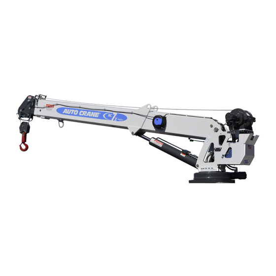
Related Manuals for Auto Crane NEXSTAR III HC-7X


Summary of Contents for Auto Crane NEXSTAR III HC-7X
- Page 1 OWNER’S MANUAL HC - 7X NEXSTAR III 477823015-0918-B Serial No. Mailing Address: Phone: 1-800-777-2760 Physical Address: P.O. Box 580697 Fax: (918) 269-6688 4707 N. MIngo Rd. Tulsa, OK 74158697 http://www.autocrane.com Tulsa, OK 74117-5904...
- Page 3 At the time of publishing this manual is accurate to the best of our knowledge. Auto Crane reserves the right to change any or all items, components and parts, necessary for any reason. This right does not obligate Auto Crane to immediately update the manual. If in doubt, please call your local Auto Crane distributor for the most up-to-date information.
-
Page 5: Table Of Contents
Table of Contents SECTION PAGE Safety Tips And Precautions ............Introduction ................General Specifications ..............Dimensions ..............Capacity ............... Reach ................Cable ................Chassis And Mounting Requirements ......... Electrical System Requirements ........Rotation ................ Hydraulic System Requirements ........Load Chart ................... 5 Qualifications And Operating Practices ........ -
Page 6: Section Page
Table of Contents SECTION PAGE Inspection Requirements ..........8.2 Inspection Classification ..........Frequent Inspection ............Periodic Inspection ............Cranes Not In Regular Use ..........Inspection Records ............Testing Requirements ............. General Repairs And Maintenance ........Maintenance Precautions ..........8.10 Adjustments And Repairs ..........8.11 Lubrication .............. -
Page 7: Safety Tips And Precautions 1
Do not attempt to lift or drag a load from the side! The boom can fail far below its rated capacity. WARNING Do not weld, modify, or use unauthorized components on any Auto Crane unit! This will void any warranty or liability. Also, failure of the crane may result. -
Page 8: Introduction
The cranes are attached to your 12-volt truck electrical system. The crane is another highly efficient Auto Crane product. The use of a maintenance-free battery is not recommended on any Auto Crane product. The recommended alternator and battery that will give the longest life with the most useful duty cycle is a 60-amp alternator with a 500 cold cranking amp battery. These specifications should be considered minimum. - Page 9 If you require additional information, please contact the Auto Crane Company at the following telephone number: 1-800-777-2760 The information contained in the manual is in effect at the time of this printing. Auto Crane Company reserves the right to update this material without notice or obligation.
-
Page 10: General Specifications
3 General Specifications 3.1 DIMENSIONS • Width: 25.5 in. (0.65 m) • Height: 36.75 in. (0.93 m) • Length: 15 ft. 3/8 in. (4.58 m), stored length • Weight: 1,870 lbs. (848 kg) 3.2 CAPACITY • 43,000 ft-lbs (6.55 ton-m) • Ft-lbs = horizontal distance from center line of rotation to free hanging weight (feet) x amount of weight (pounds). 3.3 REACH • Second boom reach: 12 ft. 5-3/8 in. to 21 ft. 6-7/8 in. • Third boom reach: 21 ft. 6-7/8 in. to 30 ft. 5-3/4in. 3.4 CABLE • 120 ft. (36.6 m) of 3/8 in. (9.5 mm) diameter aircraft quality cable. This cable has a single line breaking strength of 14,400 lbs. (6,531 kg). 3.5 CHASSIS AND MOUNTING REQUIREMENTS • 14,500 lbs. (6,577 kg) GVWR minimum. • 360,000 in-lbs. Resistive Bending Moment (RBM) • 7/8”, Grade 8-UNF Bolts. Tightened to 475 ft. lbs. • 13-1/2” Mounting hole to run hydraulic and electrical lines to the crane from the body. 3.6 ELECTRICAL SYSTEM REQUIREMENTS • Voltage: 12 VDC • Alternator: 60 amps minimum • Battery: 100 minute reserve capacity minimum. Maintenance Type battery... - Page 11 Load Chart 4 HC-7X 4560 NOTE: 1. ALL CAPACITIES SHOWN IN (LBS) 2. WEIGHT OF LOAD HANDLING 2245 DEVICES ARE PART OF THE LOAD AND MUST BE DEDUCTED FROM THE CAPACITY 1591 6255 3230 1289 2294 7000 75° 6260 1955 60°...
-
Page 12: Qualifications And Operating Practices
B. Possess the knowledge of emergency procedures and implement it. C. Demonstrate to the employer the ability to operate the specific type of equipment. D. Be familiar with the applicable safety regulations. E. Understand the operating procedures as outlined by the Auto Crane. F. Be thoroughly familiar with the crane and its control functions. HC-7X NEXSTAR III... -
Page 13: Conduct For Operators
Qualifications and Operating Practices 5 5.3 CONDUCT OF OPERATORS 1. The operator shall not engage in any practice, which will divert his attention while actually operating the crane. 2. Each operator shall be responsible for those operations under the operator’s direct control. Whenever there is any doubt as to safety, the operator shall consult with the supervisor before handling the loads. -
Page 14: Operating Near Electrical Power Lines
5 Qualifications and Operating Practices 4. During lifting care shall be taken that: A. There is no sudden acceleration or deceleration of the moving load. B. When rotating the crane, sudden starts and stops shall be avoided. Rotational speed shall be such that the load does not swing out beyond the radius at which it can be controlled. - Page 15 Qualifications and Operating Practices 5 1. Do not place any part of the crane or load inside the Danger Zone. EXCEPTIONS: A. The Danger Zone may be entered after confirmation by an appointed person the electrical distribution and transmission lines are de-energized and visibly grounded at the point work. B. The Danger Zone may be entered if insulating barriers are erected to prevent physical contact with the lines. These can’t be a part of or attached to the crane.
-
Page 16: Preparing The Crane For Operation
B. Leave the ignition on with the transmission in neutral (or park for automatic transmissions). C. Activate any crane power switches. 7. For Auto Crane units using electric and hydraulic operation: A. Engage the emergency brake. B. Place the transmission in neutral. - Page 17 Qualifications and Operating Practices 5 9. Remove the remote control from the cab or storage area. Power the remote control on. Detach the hook from the dead man. 10. The crane is now ready for operation. DURING OPERATION 1. Always boom up before rotating so the boom will clear the boom support. 2.
-
Page 18: Nexstar Lll Operation
6 NexStar lll Operation This section describes the general operation for cranes with the NEXSTAR lll control system. WARNING Before operating the Remote Control, read and understand all safety information in this manual, any manual supplements, and any applicable local, state, or federal rules and regulations. WARNING Never drive with a load suspended from the crane. WARNING Ensure personnel and objects are clear of the crane path during operation. -
Page 19: Remote Control Layout
NexStar lll Operation 6 6.5 REMOTE CONTROL LAYOUT Nextstar lll Remote Control 1. Emergency Stop Button – Push to activate. Pull to release. When activated the emergency stop button stops all outputs from the receiver. 2. Display Screen – LCD screen that displays many crane operating parameters. See Figure 4. 3. -
Page 20: Display Screen Layout
Watchdog Timer – The black dot should always be moving in a diagonal. If the timer stops, contact your Auto Crane representative. Signal Strength and Battery Life – Displays the signal strength coming from the crane. The approximate range is 300 ft. The battery displays the percent remote control battery life remaining. -
Page 21: Speed Selection
NexStar lll Operation 6 6.7 SPEED SELECTION 1. Press and hold the Link Switch in the up position. 2. While holding the Link Switch in the up position: A. Move the Left Joystick up to increase the max speed. B. Move the Left Joystick down to decrease the max speed. 3. -
Page 22: Operation-Valve Override
6 NexStar lll Operation 6.10 COUNTERBALANCE VALVE ADJUSTMENT/OVERRIDE PROCEDURE 1. With PTO disengaged and boom properly supported, remove the plug on the counterbalance valve. Install a pressure gauge (0-3000 PSI) into the port. 2. Engage PTO and insure pump flow is 8 to 9 GPM. With no load on boom, boom up to an angle of 70 degrees. Boom down and note pressure. If pressure reading is not approximately 1300 PSI, the counterbalance valve requires adjustment. -
Page 23: Transmitter Layout
NexStar lll Operation 6 6.11 Transmitter Layout LABEL DIRECTION FUNCTION GRAPHIC DESCRIPTION Sends a 12VDC signal from crane to start vehicle Engine Start Down Engine Stop Sends a 12VDC signal from crane to stop vehicle Boom Up function Down Boom Down Rotate CCW Right Rotate CW... -
Page 24: Nexstar Lll Troubleshooting
7 NexStar lll Troubleshooting 7.1 TROUBLESHOOTING FLOW CHART CRANE DOES NOT OPERATE CORRECTLY IS THERE GO TO ERROR CODE AND ERROR TROUBLESHOOTING CODE? CHART DOES IT DOES THE CRANE GO TO ELECTRICAL STOPMOVING WHEN MOVE UNEXPECTEDLY TROUBLESHOOTING YOU UNPLUGTHE WHEN A FUNCTION IS CHART CORRESPONDING NOT SELECTED? -
Page 25: Nexstar Lll Remote Control Troubleshooting Table
NexStar lll Troubleshooting 7 7.2 NEXSTAR lll REMOTE CONTROL TROUBLESHOOTING TABLE PROBLEM POSSIBLE REASON ACTION REMOTE CONTROL WILL REMOTE CONTROL EMERGENCY STOP ENSURE THE E-STOP SWITCH IS NOT TURN ON SWITCH IS DOWN OR PRESSED. PULLED UP. BATTERIES ARE DEAD OR INSTALLED ENSURE ALL SWITCHES, BUTTONS, BACKWARDS;... -
Page 26: Nexstar Lll Error Code Table
7 NexStar lll Troubleshooting 7.3 ERROR CODE TABLE ERROR CAUSE DIAGNOSIS SOLUTION CODE S0. E-STOP E-STOP ACTIVATED ALL OUTPUTS DEACTIVATE E-STOP PER OPERATION ACTIVE WILL BE PROCEDURES. DISABLED S1. CAN RX TO RECEPTION OF A CAN ALL OUTPUTS DETERMINE WHY MESSAGE(S) IS MESSAGE TIMED OUT WILL BE (ARE) NOT BEING RECEIVED. - Page 27 NexStar lll Troubleshooting 7 7.3 ERROR CODE TABLE ERROR CAUSE EFFECT SOLUTION CODE A8. 100% REACHED 100% OF RATED DISABLES REDUCE LOAD BY EITHER RETRACTING, LOAD ALARM CAPACITY BOOM DOWN, BOOMING UP, OR HOISTING DOWN. EXTEND, AND HOIST UP A9. SLOW LIFT CYLINDER HAS REDUCES THIS IS A SAFETY FEATURE THAT ROTATE ACT...
-
Page 28: Nexstar Lll Electrical Troubleshooting Table
7 NexStar lll Troubleshooting 7.4 ELECTRICAL TROUBLESHOOTING TABLE ERROR CAUSE EFFECT SOLUTION CODE CRANE MOVES JAMMED ACTIVATE E-STOP TO SEE IF VERIFY THAT NOTHING WAS UNEXPECTEDLY TRANSMITTER MOVEMENT STOPS. ACTIVATING THE FUNCTION AT THE BUTTON TIME OF MOVEMENT. IF IT WAS NOT ACTIVATED THEN REPLACE TRANSMITTER. - Page 29 NexStar lll Troubleshooting 7 7.4 ELECTRICAL TROUBLESHOOTING TABLE ERROR CAUSE EFFECT SOLUTION CODE ANTI-2 BLOCK CHECK SCREEN FOR ERROR VERIFY THAT THE TRAVELING BLOCK FOLLOWING CODE. IT WOULD READ ANTI-2 IS NOT IN CONTACT WITH BAIL. IF FUNCTIONS BLOCK ERROR. SO, HOIST DOWN AND CHECK FUNCTIONS AGAIN.
- Page 30 7 NexStar lll Troubleshooting 7.4 ELECTRICAL TROUBLESHOOTING TABLE ERROR CAUSE EFFECT SOLUTION CODE CRANE IS AT OR OVER 90% OF THIS IS A SAFETY FEATURE TO FUNCTIONS OVERLOAD IT’S RATED CAPACITY PREVENT GETTING INTO AN UNSAFE OPERATE ACTIVATED CONDITION (SUDDEN MOVEMENT OF SLOWLY HEAVY LOAD). 90% OVERLOAD WILL REMAIN ACTIVATED UNTIL LOAD IS DECREASED.
-
Page 31: Nexstar Lll Hydraulic Troubleshooting Table
TRY TO MANUALLY OVERRIDE REPLACE CARTRIDGE UNEXPECTEDLY CARTRIDGE VALVE IF UNABLE TO MOVE STEM. CARTRIDGE IS JAMMED. COUNTERBALANCE ADJUST THE COUNTER-BALANCE CONTACT AUTO CRANE FOR SET TOO LOW OUT TO SEE IF MOVEMENT PROPER SETTING OF (BOOM-UP & STOPS. COUNTERBALANCE. YOU MAY BOOM-DN) NEED TO REPLACE COUNTERBALANCE. -
Page 32: Maintenance
8 Maintenance 8.1 INSPECTION REQUIREMENTS NOTICE Reference ASME B30.5 and OSHA 1910.180 for complete inspection requirements. WARNING All inspections shall be performed by the designated personnel only. 8.2 INSPECTION CLASSIFICATION 1. Initial Inspection A. Prior to initial use, all new, altered, modified, or extensively repaired cranes shall be inspected by a designated person to ensure compliance with provisions of this standard. 2. -
Page 33: Periodic Inspection
Maintenance 8 B. General corrosion. C. Broken or cut strands. D. Use care when inspecting sections of rapid deterioration around flange points crossover points, and repetitive pickup points on drums. E. Inspect number, distribution, and type of visible broken wires. NOTICE Continued use of rope depends upon good judgment by a designated person in evaluating remaining strength in a used rope after allowance for deterioration disclosed by inspection. -
Page 34: Cranes Not In Regular Use
8 Maintenance 12. Inspect hydraulic cylinders for the following problems: A. Driving caused by fluid leaking across piston. B. Rod seals leaking. C. Leaks at welding joints. D. Scored, nicked, or dented cylinder rods. E. Damaged case (barrel). F. Loose or deformed rod eyes or connecting joints. 13. Inspect hydraulic filters for evidence of rubber particles on the filter elements indicating possible hose, O-ring, or other rubber component deterioration. -
Page 35: General Repairs And Maintenance
Maintenance 8 WARNING All testing shall be performed by designated personnel only. Prior to initial use, all new, altered, modified, or extensively repaired cranes shall be inspected by a designated person to ensure compliance with provisions of this standard. 1. Test all functions to verify speed and operation. 2. Ensure all safety devices are working properly. 3. Confirm operating controls comply with appropriate function labels. -
Page 36: Lubrication
8 Maintenance B. Critical parts of the crane structure which are cracked, bent, broke, or excessively corroded. C. Crane hooks showing cracks, damage, or corrosion shall be taken out of service. Repairs by welding are recommended. 4. If bleeding the hydraulic system is required, run each crane function until smooth operation of that particular function is noticeable. -
Page 37: Paint Finish Maintenance
The paint finish on Auto Crane products can become damaged during normal use when chipped, scratch, exposed to harsh chemicals, cleaned with pressure washers, or similar. During periods when the truck is exposed to salt or other corrosive chemicals, wash Auto Crane products weekly. Inspect the paint finish monthly or when washed. Immediately repair any exposed bare metal or rust. Repair damaged paint on Auto Crane products with the following procedure: 1. -
Page 38: Lubrication And Maintenance Schedule
8 Maintenance 8.15 LUBRICATION AND MAINTENANCE SCHEDULE Service Instructions Daily Weekly 3 Months 6 Months Yearly Performed Load Hook Inspect hook and latch for deformation, cracks, and corrosion. Cable Drum Ensure cable is wound evenly on drum. Hoist/Boom Check for flattening, Cable kinks, broken strands. Hyd. Hoses Visual inspection. -
Page 39: Lubrication Points
1. Use only authorized parts. Any damage or malfunction caused by the use of unauthorized parts is not covered by Warranty or Product Liability. 2. Once a bolt has been tightened to specification then removed, the bolt should be replaced with a new one. Auto Crane Company recommends this crane be serviced per the “Crane Inspection Log” P/N 999978. Fill these logs in at the intervals noted and kept as a permanent record. Additional copies are available from your local distributor. -
Page 40: Nexstar Lll Cartridge Maintenance
8 Maintenance 8.17 NEXSTAR lll CARTRIDGE MAINTENANCE Verify movement in ports while manually overriding cartridge Use the following procedure to inspect the cartridge for proper operation. 1. Clean the area around the valve spool before it is removed from the valve bank. 2. -
Page 41: Crane Mounting And Installation 9
9. Ensure the Owner’s Manual is delivered to the customer. 10. Install voltage switching unit inside compartment safe from weather and contamination. 11. See following page for additional electrical installation. 12. For additional help: Call the Service Department at the Auto Crane Company, 1-800-777-2760, located in Tulsa, OK. IMPORTANT! -
Page 42: Stability Chart Installation
This decal is to alert the user of the available crane capacities around the vehicle. • 479824002 decal will be installed on an Auto Crane body that was outfitted with an Auto Crane crane and Auto Crane outriggers. Auto Crane has designed the body, crane and outrigger to have stability based on the chart below: HC-7X NEXSTAR III... - Page 43 Crane Mounting and Installation 9 • 479824003 decal will be installed on an Auto Crane body that was not outfitted with an Auto Crane crane and Auto Crane outriggers. Auto Crane has designed the body, crane, and outrigger to have stability based on the chart. The stability chart provides lines to write in the tested stability percentage at each section below:...
-
Page 44: Nexstar Lll Counterbalance Valve Adjustment
9 Crane Mounting and Installation 9.2 NEXSTAR lll COUNTERBALANCE VALVE ADJUSTMENT WARNING Do not try to adjust valves while the boom is moving 1. Ensure the PTO is disengaged and the boom is properly supported. 2. Remove the plug on the counterbalance valve. 3. -
Page 45: Decal Layout
Decal Layout P/N: 477624050 10 SECTION A-A HC-7X NEXSTAR III... - Page 46 DECAL ANGLE INDICATOR CS 320318001 DECAL ANGLE INDICATOR SS 460169000 DECAL WARNING, REMOTE CONTROL 040632000 DECAL WARNING - OVERLOAD 360034000 DECAL AUTO CRANE LOGO 040824000 DECAL, AMERCIAN FLAG, MADE IN THE U.S.A. 040579000 DECAL OPERATION INSTRUCTIONS 040580000 DECAL TRAINED OPERATOR HC-7X NEXSTAR III...
-
Page 47: General Assembly
General Assembly P/N: 477000006 11 20 17 18 19 11 12 12 24 23 22 24 22 SLAVE MASTER UNIT UNIT SECTION A-A DETAIL B DETAIL C SECTION D-D HC-7X NEXSTAR III... - Page 48 11 General Assembly P/N: 477000006 ITEM NO. PART NO. DESCRIPTION 477200101 PEDESTAL ASS'Y, HC-7X, NEXSTAR III 477624050 DECAL LAYOUT, HC-7X, NEXSTAR 479200101 BOOM ASSEMBLY, 30', 49K MAXIMUM MOMENT 477200105 SHIP KIT, HC-7X, NEXSTAR III 479200179 PIN, PIVOT 021600000 WASHER FL 1/2 021500000 WASHER, SP LK 1/2 017701000 NUT HX 1/2-13 UNC...
-
Page 49: General Dimensions 12
General Dimensions 12 HC-7X NEXSTAR III... -
Page 50: Pedestal Assembly
13 Pedestal Assembly P/N: 477200101 56 77 58 57 21 20 15 DETAIL A DETAIL B TYP. BOTH SIDES HC-7X NEXSTAR III... - Page 51 Pedestal Assembly P/N: 477200101 13 DETAIL C BU BD RETURN PRESSURE VALVE BANK HOSING DETAIL HC-7X NEXSTAR III...
- Page 52 13 Pedestal Assembly P/N: 477200101 31 77 58 57 57 SECTION D-D HC-7X NEXSTAR III...
- Page 53 Pedestal Assembly P/N: 477200101 13 ITEM NO. PART NO. DESCRIPTION 479200180 BASE PLATE WELDMENT 479200160 SLEWING DRIVE 239020000 WASHER FL 5/8 HARDENED 490306000 HX HD 5/8-11 X 2.00 GR8 479200185 5/8-11 SHCS, ZINC PLATED, 3 IN LG 020600000 WASHER 5/16 LOCK SS 007800000 SCREW HX HD 5/16-18 UNC X 2 LG 479200161...
- Page 54 13 Pedestal Assembly P/N: 477200101 ITEM NO. PART NO. DESCRIPTION 366359000 FITTING, -8 SAE / -8 JIC, SWIVEL, STR 479200201 SPACER, NYLON, 3/8 ID, 3/4 OD, 3/8 LG 479200206 HARNESS, NEXSTAR III, HC-8X, HC-7X 479200205 COVER, VALVE 366823240 PIN, 3/16 W/LANYARD 020901000 WASHER FL 5/16 007805000 5/16-18 UNC x 1-1/2...
- Page 55 HC-7X NEXSTAR III...
-
Page 56: Hoist Assembly
14 Hoist Assembly P/N: 123340 ITEM NO. PART NO. DESCRIPTION 234189 DRUM ASSEMBLY 306042 PISTON-BRAKE 315004 ANCHOR- CABLE 338300 END BRG-MOTOR END 338301 END BRG-GEAR HSG. 338302 HSG-BRAKE 346045 PIN-BRAKE 357513 SHAFT- INPUT 362291 SPACER - FOOT MTG 362284 SPACER - TIE PLATE 402120 BEARING-GARLOK BRG. - Page 57 Hoist Assembly P/N: 123340 14 ITEM NO. PART NO. DESCRIPTION 414548 CAPSCREW-1/2-13 NC X 1-1/2, HXHD, Z/P, G5 414854 SCREW-1/4-20 NC X 1/2 LG, RDHD, SLOT, Z/PL 414926 SETSCREW-3/8-16 NC X 1, SOCKET, NYLON 414948 CAPSCREW-1/2-13 NC X 1-1/4 LG, SOCKET HD 416016 SETSCREW 1/4-20 NC X 1/4 HX SOCK HD CUP 416080...
-
Page 58: Boom Assembly
15 Boom Assembly P/N: 479200101 45 45 15 14 36 37 35 14 17 32 33 ITEM NO. PART NO. DESCRIPTION 479200120 WELDMENT, LOWER BOOM, HEX 239000000 ZERK DRIVE GR 479200130 WELDMENT, MID BOOM, HEX 020901000 WASHER FL 5/16 020600000 WASHER 5/16 LOCK SS 479200162 5/16-24 BHCS, 1/2 LG, ZINC PLATED, GR 5 HC-7X NEXSTAR III... - Page 59 Boom Assembly P/N: 479200101 15 ITEM NO. PART NO. DESCRIPTION 022102000 WASHER FL 3/4 018600000 NUT HX NYLK 3/4-16 UNF 016100001 SCREW, FLAT HEAD, 1/4-28 X 1, ZINC PLATED, GR 5 460177162 SCREW SOC HD 5/8-11 UNC X 3/4 LG 021200000 WASHER FL 3/8 021100000 WASHER SP LK 3/8 479200169...
-
Page 60: Traveling Block Assembly
16 Traveling Block Assembly P/N: 480854000 ITEM NO. PART NO. DESCRIPTION 480860000 TACKLE LOWER 480859000 SIDE PLATE TRAVELING BLOCK 480366000 HOOK SWIVEL 6 METRIC TON 480861000 SHEAVE ASSY 3/8 ROPE 490313000 BOLT, SHEAVE W/ZERK FITTING 018600000 NUT HX NYLK 3/4-16UNF CP 360605000 PIN, BLOCK 366813000 PIN HITCH... -
Page 61: Hydraulic Power Unit
Hydraulic Power Unit P/N: 366823251 17 ITEM NO. PART NO. DESCRIPTION 366823901 COIL, 5/8” DIA 12 VDC DEUTSCH 366823902 CARTRIDGE, SIZE 4W 3P CLSD CTR 366823906 VALVE, LOGIC SPOOL TYPE, 218 PSI 366823960 CARTRIDGE, 2-WAY UNLOADER, EXTENDED MANUAL OVERRIDE 366823903 CARTRIDGE, SIZE 4W 3P FLOAT CTR 366823905 VALVE, RELIEF DIRECT-ACTING (2750PSI) 480195000 FITTING 45 6-SAE/6-JIC... - Page 62 17 Hydraulic Power Unit P/N: 366823251 11.01 5.00 4.31 10.50 5.00 1.25 2.09 6.38 3.16 4.69 7.31 5.62 8.84 2.00 3.56 HC-7X NEXSTAR III...
- Page 63 Hydraulic Power Unit P/N: 366823251 17 HC-7X NEXSTAR III...
-
Page 64: Wiring Harness
18 Wiring Harness P/N: 479200206 HC-7X NEXSTAR III... - Page 65 Wiring Harness P/N: 479200206 18 CONNECTOR ID CONNECTOR DESCRIPTION CONNECTOR DESCRIPTION RECEIVER 18 PIN CONNECTION BOOM ANGLE SENSOR RECEIVER 30 PIN CONNECTION PENDANT CONNECTION USB CONNECTION ALARM LIGHT BOOM DN ADDRESS BOOM UP BOOM PT SWING CW DIRTY FILTER SWING CCW CCW LIMIT SWITCH BOOM RETRACT CW LIMIT SWITCH...
-
Page 66: Electrical Schematic
19 Electrical Schematic P/N: 479200207 HC-7X NEXSTAR III... - Page 67 LIMITED WARRANTY 1 YEAR PURCHASED REPLACEMENT PARTS Auto Crane will warranty to the consumer for a period of (1) year from the date that a new Auto Crane replacement part was purchased from an authorized Auto Crane distributor. Each new Auto Crane part they sell will be free under normal use and service from defects in material and workmanship.
- Page 68 2 YEAR PARTS AND LABOR Auto Crane will warranty to the consumer for a period of (2) years parts and labor from the date of purchase. Each new Auto Crane unit they sell will be free under normal use and service from defects in material and workmanship.
- Page 72 HC-7X NEXSTAR III...
Need help?
Do you have a question about the NEXSTAR III HC-7X and is the answer not in the manual?
Questions and answers