Table of Contents
Advertisement
Quick Links
IMS
E3T-
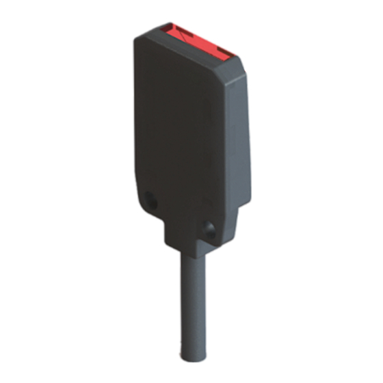
Compact Photoelectric Sensor
INSTRUCTION MANUAL
! WARNING
Thank you for selecting IMS product.This sheet primarily describes precautions
required in installing and operating the product.Before operating the product,read
the sheet thoroughly to acquire sufficient knowledge of the product.For your
convenience,keep the sheet at your disposal.
! CAUTION
Failure to follow these instructions may result in serious injury or death:
Fail-safe device must be installed when using the unit with machinery that may
cause serious injury or substantial economic loss. (e.g. nuclear power control,
medical equipment, ships, vehicles, railways, aircraft, combustion apparatus,
safety equipment, crime/disaster prevention devices,etc.)
Failure to follow these instructions may result in product damage:
Do not use this unit over rated voltage;
Do not use this unit where there is flammable or explosive gas;
Do not use this unit where there is vibration or impact;
In cleaning the unit, do not use water or an oil-based detergent.
Ordering information
E3T D
1
M
N
L
T
Sensitivity
Operation mode
Output
Sensing distance unit
Sensing distance
(slot series use 30/50 to refer slot distance)
(
Sensing method
slot series is none
Item
Control box
Functions of indicators and keys
LED1:sensor output status
LED2:transmission power adjustment status
Key1:Increase the transmitting power
Key2:Reduce the transmitting power
Operation instruction
Short press key1 one time:Increase the transmitting power slightly. When the power
up to the maximum, LED2 will blink at an interval of 0.25s.
Short press key2 one time:Decrease the transmitting power slightly. When the power
down to the minimum, LED2 will blink at an interval of 0.5s.
Long press key1:When the long press time reaches 2s, the transmitting
power will continue to increase. The voltage will no longer change after release the
button. When the LED2 flashing, it means the power reaches the maximum.
Long press key2:When the long press time reaches 2s, the transmitting power will
continue to decrease. The voltage will no longer change after release the button.
When the LED2 flashing, it means the power reaches the minimum.
Save setting:The parameter will be automatically saved to EEPROM and does not
need to be set next power on.
C
(Light source code)
Connection type
L
C
Response time
M
T
L
D
S
N
P
O
D
C
A
M
Number Sensing distance
T
D
)
R
V
B
E3T
Specifications
Sensing method
NPN
Model
PNP
Sensing distance
Sensing object
Min. sensing target
Hysteresis
Response time
Power supply
Current consumption
Light source
Operation mode
Output
Load current
Circuit protection
Indicators
Insulation resistance
Noise strength
Dielectric strength
Vibration resistance
Shock resistance
Ambient illumination
Cable type
Ambient temperature
Connector type
Ambient humidity
1ms
0.25ms
Degree of protection
available
Material
Fixed
Light on
Cable
Dark on
Selectable
Accessory
NPN
Weight
PNP
NPN+PNP
(*1) Reflector:KY-R4
5V
Relay
(*2) Reflector:KY-6
Analog
Unit:mm
Control output circuit diagram
Unit:m
NPN open collector output
①
Through-beam
Diffuse reflective
Retro reflective
Convergent Reflective
Polarization opaquing
Photoelectric sensor
Stability
(green)
Operation
(red)
Key1
Key2
PNP open collector output
②
Stability
(green)
Operation
(red)
Through-beam
Diffuse reflective
E3TT
-N
E3TD
E3TT
-P
E3TD
30/50/70mm(Non-glossy
0~500mm/1m
white paper 50*50mm)
Opaque materials of
Opaque materials
max. φ2mm
φ0.5mm(sensing distance
Opaque materials of
10mm)
φ2mm
Max. 20% at rated sensing
distance
Max.1ms
10~30VDC(including ripple Max.10%(p-p))
Max. 20mA
Red LED(650nm)
Light ON/Dark ON
NPN or PNP open collector output
Max. 100mA (Residual voltage:Max. 3V),Load voltage:Max. 26.4VDC
Reverse polarity protection、output short-circuit protection、
Over current protection
Operation indicator:Red,Output indicator:Green
Min. 20MΩ ( at 500VDC megger )
±240V the square wave noise(pulse width:1μs)by the noise simulator
1000VAC 50/60Hz for 1 minute
1.5mm or 300m/s² amplitude at frequency of 10 to 55Hz in each of
X,Y,Z direction for 2 hours
500m/s² in X,Y,Z directions for 3 times
Sunlight:Max. 11,000lx ,
Incandescent lamp:Max. 3,000lx (Receiver illumination)
Operation:-25 ~ 55 ℃,Storage:-40 ~ 70 ℃(with no icing)
Operation and storage:35 ~ 85 %RH(with no condensation)
IP64(IEC standards)
Case:PBT,Lens:PMMA
φ2.6mm,3P,Length:2m (Through-beam type:3P/4P,Length:1.5m)
(AWG28,Core wire diameter 0.08mm,No. of core wire:16,Insulator
out diameter:0.8mm)
Fixing bracket,screw
Approx. 40g
(Brown)+V
(Black)Output
Over
current
protection
Blue(0V)
(Brown)+V
Over
current
protection
(Black)Output
Blue(0V)
Retro reflective
-N
E3TR
-N
-P
E3TR
-P
100mm(*1)
200mm(*2)
Opaque materials
φ2mm(sensing
distance100mm)
Approx. 25g
Load
+
10~30VDC
-
Max. 100mA
+
Max. 100mA
10~30VDC
-
Load
Advertisement
Table of Contents

Related Manuals for IMS E3T Series

Summary of Contents for IMS E3T Series
- Page 1 Hysteresis distance Response time Max.1ms Thank you for selecting IMS product.This sheet primarily describes precautions required in installing and operating the product.Before operating the product,read Power supply 10~30VDC(including ripple Max.10%(p-p)) the sheet thoroughly to acquire sufficient knowledge of the product.For your Current consumption Max.
- Page 2 Connections Mounting & Adjustment Through-beam Diffuse reflective Installation Confirm that the sensing surface of sensor is parallel with the surface of each sensing object. Please use screw M2 to mount the sensor,set the tightening torque under 0.3N.m. ※1:Load connection for NPN output; ※2:Load connection for PNP output;...
Need help?
Do you have a question about the E3T Series and is the answer not in the manual?
Questions and answers