
Related Manuals for Soltec CFM-Lite


Summary of Contents for Soltec CFM-Lite
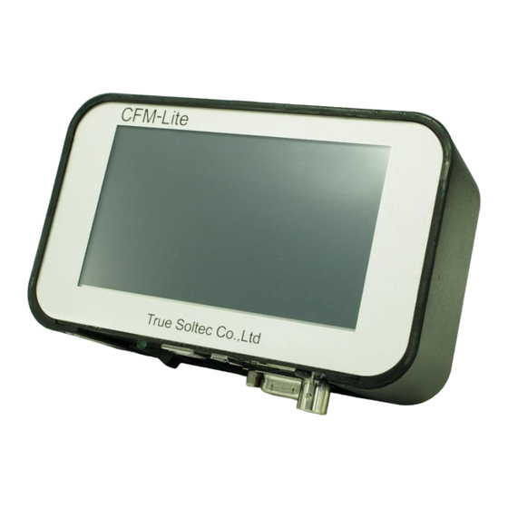
- Page 1 CFM-Lite General instruction manual General Instruction Manual CRIMP FORCE MONITOR CFM-Lite Ver 1.4 1 / 58...
- Page 2 CFM-Lite General instruction manual UPDATED HISTORY Version Date Updated by Details Version 1.0 2017.10.24 Masato Sato Version 1.1 2017.11.13 Masato Sato 1. Overview is updated Version 1.2 2018.12.14 Masato Sato 1.2 description for dongle is updated Version 1.3 2020.01.22 Suzuki Tomomi Update functions of CFM-Lite (FW V1.17, SW V1.0.4.5)
- Page 3 CFM-Lite General instruction manual INDEX Overview ................................. 5 1.1. Introduction ............................5 1.2. Main Unit and Accessories ......................5 1.3. CFM-Lite Specifications ........................7 1.4. I/O pin assignment ..........................7 1.5. Detectable Defects ..........................8 1.6. Wire size..............................12 Tolerance ................................13 CFM-Lite Operation ............................
- Page 4 CFM-Lite General instruction manual 3.2.10. Brightness Adjustment ......................35 3.2.11. Preload Setting ..........................35 3.2.12. Auto Trigger Check ........................36 3.2.13. Capture raw force data ......................37 3.2.14. Head Room ............................. 39 3.2.15. Communication Error ......................... 44 Technical Description ............................45 4.1.
- Page 5 1. Overview 1.1. Introduction Crimp Force Monitor CFM-Lite is integrated into manual crimping machine or semi- automatic crimping machine, to check the crimp quality through monitoring crimping force. All operations are performed via the LCD touch panel on the main unit. Standard settings and operations are simplified with only crimping force curve display and some buttons on the main screen, so that customers can handle it easily.
- Page 6 Accessories Packed together Non packed together CFM-Lite Main Unit PC software (Download from True Soltec website) Sensor: General instruction manual and Installation manual ・Standard: PSS type (Download from True Soltec website) ・Others: FTW or FTC model.
- Page 7 CFM-Lite General instruction manual 1.3. CFM-Lite Specifications Outer dimensions W 137mm x H 84mm x D 50mm Analog sensor Resolution 12bit signal Max sampling rate 20kHz Sensor FTW series (ring type force sensor, cable output, 0.1 to 10 ton) PSS series (piezo strain sensor, high /middle / low sensitivity...
- Page 8 CFM-Lite General instruction manual 1.5. Detectable Defects This section describes all the defects that CFM-Lite can and cannot effectively detect, given the condition that crimping machines, applicators, and tools are in good performance. Crimped terminal Wire barrel Fitting part Insulation...
- Page 9 CFM-Lite General instruction manual A) Defects that can be detected nearly 100% (major defects) a) High feed (Wire barrel pinches the insulation) Example of high feed (detectable) Insulation Wire barrel Fitting part Insulation barrel Wire This is the case where the wire barrel pinches the insulation (deep-feed defect).
- Page 10 CFM-Lite General instruction manual B) Defects that are difficult to detect a) High feed (Wire barrel does not pinch the insulation) Example of deep feed (hard-to-detect case) Wire barrel Fitting part Insulation Insulation barrel Wire This is the case where the wire barrel does not pinch the insulation (deep-feed defect).
- Page 11 CFM-Lite General instruction manual d) Deformation of the insulation barrel Unlike to the wire barrel, the crimping force applied to the insulation barrel is quite small. Therefore, even if the insulation barrel is deformed, the curve does not change significantly.
- Page 12 This curve is of either strand being cut / out, or low feed. The force curve is lower at all areas T1, T2, T3. Crimped terminal sample (Low feed) 1.6. Wire size The smallest wire size that CFM-Lite can inspect, is AWG28. 12 / 58...
- Page 13 CFM-Lite General instruction manual 2. Tolerance CFM-Lite has 5 tolerance levels. No. 1 is the smallest, while No. 5 is the biggest. In each judgement area, if the result value (%) exceeds the +/- limit, CFM-Lite judges this is error.
- Page 14 CFM-Lite General instruction manual 3. CFM-Lite Operation 3.1. Main Unit 3.1.1. Start up It is shown when the turning on the main unit. It automatically goes to TEACH screen after 3 seconds. version:0.0XX CPUID:XXXX 3.1.2. TEACH This is TEACH screen.
- Page 15 OPE (operation) mode. It is ON during production. Press this button to cancel TEACH mode and go to OPE screen. At this mode, CFM-Lite judges the crimp quality. If it is defective, CFM- Lite stops the machine operation. During TEACH: Description Force curve The actual force curve is shown in yellow.
- Page 16 Meas Show measurement time of the force curve (right display to left of the force curve screen) in mSec. This is automatically determined by CFM-Lite at TEACH mode. Numerical Show judgement result of T1 Display - Upper When error occurs, it is shown in red.
- Page 17 CFM-Lite General instruction manual 3.1.3. OPE (Operation) This is OPE (operation) screen during production. Description: TEACH button. Move to TEACH screen. OPE button. Here, CFM is already in OPE mode so this button is deactivated. During OPE: Description Force curve The actual force curve is shown in yellow.
- Page 18 CFM-Lite General instruction manual Show CPK value. CPK is calculated based on the variation of measured value and tolerance of T2 area. 3.1.4. Auto Trigger Check When Auto trigger function does not work well, you can check if the Trigger Level is correct.
- Page 19 CFM-Lite General instruction manual 3.1.6. Sensor Error This screen appears when the sensor is not connected to the main unit. After confirming the sensor connection, press X button at the bottom of the screen to reset it. 19 / 58...
- Page 20 CFM-Lite General instruction manual 3.1.7. Tolerance Setting At OPE mode, press the tolerance number at the bottom of the screen to move to tolerance setting screen. Graph in the middle Description: Tolerance number button (unselected state) Tap your preferred tolerance number to activate it.
- Page 21 CFM-Lite General instruction manual 3.1.8. Parameter Screen This screen appears when the parameter is opened on PC software. You cannot enter this screen when in OPE mode. It will be closed automatically when the parameter screen on the PC is closed.
- Page 22 CFM-Lite General instruction manual 3.1.10. Initialize Parameter To initialize the parameter of CFM-Lite, press the logo True Soltec on the upper left of the screen for 3 seconds when it starts up. ※All Dongle protections should be on if CFM is initialized by inserting a Dongle key ※All Dongle protections should be off if CFM is initialized without a Dongle key.
- Page 23 The data of force curves is automatically saved in the USB memory (in form of a file) when it is inserted to the USB port of CFM-Lite. The file is named as “YYYYMMDDHHMMSS.dat” in the root folder of the USB memory.
- Page 24 CFM-Lite General instruction manual Reset the main unit when an error happens. Move to Parameter screen for setting parameters. Open Configuration screen for changing settings of PC software. Open Utility screen, where force curve data can be saved or loaded.
- Page 25 Adjust the brightness of LCD screen on the main unit. Preload This is used for preloading the base plate to fix the base plate type sensor (FTW series), when PSS sensor is not used. For details, see “CFM-Lite installation manual”. 25 / 58...
- Page 26 CFM-Lite General instruction manual Auto Trigger This is used for checking the possible causes when Auto Trigger Check does not work well. For details, see 3.2.14 Auto Trigger Check (page 36). Head room This can check how accurate the production with CFM works, like detecting error and how stable it is.
- Page 27 CFM-Lite General instruction manual When set to 0%, waveform acquisition will start with the noise level alone. Trigger Delay This becomes effective when Switch (Fall) or Switch (Rise) is selected. It delays the timing of starting capturing the force curve by the number set in mSec.
- Page 28 CFM-Lite General instruction manual which means 40% of the height of the peak. In case of using servo crimping machine, it is suggested to set at 70% on the left, to make the judgement correctly. Adaptive Update the reference force curve during production, as the crimping force starts to change due to thermal elongation of the machine, after it is being used for a while.
- Page 29 CFM-Lite General instruction manual This point is also the end position of T2. T3 End The end point of T3 area is set by %. CFM searches from the peak to the right. The first point at which the specified % is reached, is decided as T3 end.
- Page 30 CFM-Lite General instruction manual Hide Trigger Button Hides the trigger level on the screen. EJECT Set the conditions for outputting the Eject signal. This signal is sent to the crimping machine each time the crimping is completed. Eject signal is 100mSec pulse signal output.
- Page 31 CFM-Lite General instruction manual 3.2.6. Configuration Settings Set the configuration of PC software. Description: Path to Head room Executable file Set the executable file path in the folder where Head room software is installed. Normally this is fixed. Language Choose a language to display on Pro- Lite.
- Page 32 CFM-Lite General instruction manual 3.2.7. Utility Settings Save Data File Save the force curve data collected by Pro-Lite as a file. Load Data File Open the force curve data file saved in PC Exit Menu Close Utility screen. A) Save Data File Click 「Save Data File」...
- Page 33 CFM-Lite General instruction manual B) Load Data File Press 「Load Data File」 button → At the popped up window, select the file you want to view and click Open. 3.2.8. Display Force Curve Data Description: Reselect the file you want to view...
- Page 34 CFM-Lite General instruction manual 3.2.9. Area Modification It is possible to adjust the judgement areas T1, T2, T3 by one of the following ways: ・ Change the values of each area ・ Drag and drop the vertical lines to your preferred positions...
- Page 35 CFM-Lite General instruction manual 3.2.10. Brightness Adjustment Brightness of the LCD screen on the main unit can be changed by moving the slider bar. Close Save the current setting and close the screen 3.2.11. Preload Setting This is used for sensor preload.
- Page 36 CFM-Lite General instruction manual 3.2.12. Auto Trigger Check This function is used for checking Auto Trigger when it does not work correctly, by capturing raw force data. Description: Save all settings to Parameter and close the window. Cancel Discard all settings and close the window.
- Page 37 CFM-Lite General instruction manual 3.2.13. Capture raw force data Signal line of the external trigger Trigger level Raw force data from the sensor Description: Blue line This shows the status of the external trigger sensor. It is in open contact of the trigger sensor when this line is on...
- Page 38 CFM-Lite General instruction manual Usage: (1) Use an external trigger sensor Check the position of the upper blue line and the yellow force curve. If they are far apart from each other, either adjust the external trigger sensor or set appropriate Trigger Delay.
- Page 39 CFM-Lite General instruction manual 3.2.14. Head Room The performance (accuracy) of CFM-Lite depends on the combination of the terminal and wire, as well as the condition of the crimping machine and its applicator. In order to inspect how accurate CFM can work as “a monitor”, you can refer to 2 indicators: Head room rate (%), and Normal dispersion rate (%).
- Page 40 CFM-Lite General instruction manual Normal dispersion (%) Normal dispersion shows how much the peak force fluctuates. This figure should stay less than 1% in order for CFM to make stable judgements. It works by collecting the peak-force data of 30 good crimps, and then automatically calculating the average of them in %.
- Page 41 CFM-Lite General instruction manual B) Setting Threshold At the bar graphs, drag the red horizontal line to between the gap of good crimp and crimp without wire. → All the graphs over the red line will then turn blue, whereas those below the red line are shown in red (picture below).
- Page 42 CFM-Lite General instruction manual Other Settings Description Tool Select an item to measure in the Head room (Peak/ T1/ T2/ T3) The measuring unit changes according to the selected item. Language Choose language Help Display software version Back Close Head room...
- Page 43 CFM-Lite General instruction manual Normal crimping This figure represents the position of the red horizontal line / Terminal only in the bar graph (mV). crimping Either entering a new number or directly dragging the line Threshold (※) will change this threshold.
- Page 44 This dialogue appears when a communication error occurs during logging on Description Retry Try to connect with CFM-Lite again. Check the power of the main unit and the connection of USB cable. Cancel “Switched offline as a port error occurs” window pops up.
-
Page 45: Technical Description
CFM-Lite General instruction manual 4. Technical Description In this section, the details of each function will be explained further (e.g. how to maintain the system, how to upgrade the program, etc.) 4.1. Good / Bad Judgement (T1/T2/T3/TD) After being captured, a force curve is automatically divided into 3 areas: T1, T2, and T3. - Page 46 CFM-Lite General instruction manual T1 area T1 Start T2 Start T1 area corresponds to the start of crimping the terminal. The crimping tool starts touching the terminal, the wire barrel is pushed down, and the force increases, then the force curve goes up.
- Page 47 CFM-Lite General instruction manual T3 area Peak force (lower dead point of the machine ram) T3 Start T3 End T3 area corresponds to the end of pushing the wire barrel down to the lower dead point of the machine ram, and from the lower dead point to the home position of the ram.
- Page 48 CFM-Lite General instruction manual 4.2. Maintenance for Applicator and Crimping tools. The role of CFM-Lite in the crimping production is to capture a crimping force and judge whether this crimp is qualified or not, via this force. Therefore, if the crimping force is unstable, CFM-Lite cannot judge it correctly.
- Page 49 CFM-Lite General instruction manual B) Base plate The maintenance for the base plate is significantly important no matter where the sensor is installed. E.g. PSS sensor is attached to the machine body to get the strain after crimping, base plate type sensor, or machine ram type sensor.
-
Page 50: Troubleshooting
CFM-Lite General instruction manual 5. Troubleshooting When facing problems with using CFM-Lite, refer to troubleshooting to help to solve problem. 5.1. Major defects which must be detected are not detected Detecting the major defects, e.g. crimp without wire (terminal only), no strip crimp, or double terminal crimp are absolutely essential. - Page 51 CFM-Lite General instruction manual Possible cause 3: Incorrect area settings of T1, T2, and T3, which causes CFM to make wrong judgement If the division lines of each judgement area are incorrect as shown below, it possibly makes wrong judgement. The initial value of each division lines are as follows: ・...
- Page 52 To know if the size of the terminal and wire is suitable to detecting defect with CFM-Lite, use Hear Room software.
- Page 53 If the machine expansion is unstable to have fluctuating force curve, use the base plate type FTW series. Refer to “CFM-Lite Installation Manual” for details. Possible cause 2: Applicator is not in good condition or crimping tools wears, which results in the force curve variation.
- Page 54 The cause of the noise peak is cause by mechanical, electrical problem, or etc. In such case, set an appropriate Trigger Level by Auto Trigger Check screen, or use external trigger with proximity sensor. See the different document “CFM-Lite installation manual” how to install the external trigger.
- Page 55 CFM-Lite General instruction manual 5.6. No force curve is captured when the terminal is crimped Even with good crimp, the force curve is not captured, which means CFM-Lite does not react, is possibly caused by the following cause. Possible cause 1: Incorrect Auto Trigger setting...
- Page 56 5.10. No terminal crimp is detected after crimping If there is no terminal crimp (wire only) detected by CFM-Lite, the force is too small to reach the Trigger Level, the force is not recognized as the force curve. Adjust the Trigger Level to appropriate number. However, too low Trigger Level makes too sensitive capturing force.
- Page 57 CFM-Lite General instruction manual 6. Index Minimum wire size ........... 12 A O Adaptive ............28 Alignment ............27 OPE ..............17 D P Dongle ............26 Parameter ............21 Pro-Lite ............23 E S EJECT ............30 Sensor error ............ 19 F...
-
Page 58: Warranty
However, if the failure was caused by the reason attributable to the users such as improper operation, or to something other than True Soltec, this is not covered by the warranty even if within warranty period. True Soltec shall make this judgement.
Need help?
Do you have a question about the CFM-Lite and is the answer not in the manual?
Questions and answers