
Related Manuals for Soltec CFM-Lite


Summary of Contents for Soltec CFM-Lite
- Page 1 CFM-Lite Installation Manual CFM-Lite Installation Manual Crimp Force Monitor CFM-Lite Ver 1.1 1 / 64...
- Page 2 CFM-Lite Installation Manual Update history Version number Date Updated by Detail Version 1.0 2017.10.24 Masato Sato Version 1.1 2018.12.14 Masato Sato 1.1 & 2.1 description for dongle is updated. 2 / 64...
-
Page 3: Table Of Contents
CFM-Lite Installation Manual CONTENTS Overview ......................... 5 1.1. The main unit, standard accessories and optional accessories ......5 1.2. Connection of accessories ..................9 1.3. Main specifications of the unit .................. 9 1.4. Terms explanation ....................10 1.5. Input and Output ....................12 1.6. - Page 4 CFM-Lite Installation Manual 3.5. How to upgrade the program of main unit ............. 61 4 / 64...
-
Page 5: Overview
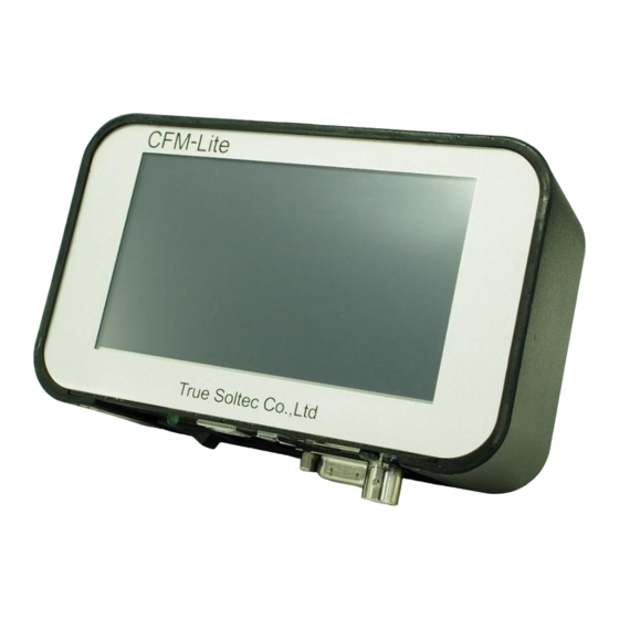
CFM-Lite Installation Manual 1. Overview This manual guides you the way how to install the system successfully. 1.1. The main unit, standard accessories and optional accessories Front All are operated via the touch panel in the front. Only the power switching button is located at the bottom. - Page 6 CFM-Lite Installation Manual Bottom USB-A type port for USB USB-B type port for Dongle key port memory USB-AB cable Sensor input Serial No. seal D-sub 9 pin port AC adaptor Power switch Power LED for I/O cable port FG (Frame Ground) must be connected firmly to the earth via e.g. the earth terminal of the table tap, crimping machine, the formal earth terminal prepared by the factory in order to prevent the external noise.
- Page 7 BNC cable I/O cable 1.5 m long BNC cable connects the 1.5 m long Input and Output cable force sensor and CFM-Lite main unit. with D-sub 9 pins connector for connecting CFM-Lite and the machine control Mounting bracket...
- Page 8 CFM-Lite Installation Manual Photos of non-packed together PC is to be normal type in the market. USB cable is available in the market, too. USB cable (AB type) B connector A connector 8 / 64...
-
Page 9: Connection Of Accessories
CFM-Lite Installation Manual 1.2. Connection of accessories BNC cable PSS sensor Dongle I/O cable USB-AB cable AC adapter 1.3. Main specifications of the unit Outer dimensions W 137mm x H 84mm x D 50mm Analog sensor Resolution 12bit signal Max sampling rate 20kHz Sensor FTW series (ring type force sensor, cable output, 0.1 to 10 ton) -
Page 10: Terms Explanation
(= good ) force data (reference force curve) to judge if it is a good crimping or defect. Operation = OPE.: It is a mode of CFM-Lite. It controls data if it is good or bad. Production is done under OPE mode. - Page 11 CFM-Lite Installation Manual Eject signal: For more advanced machines using automatic running system will use this signal as the confirmation of good crimp completion. The machine will receive this pulse signal to take the next cycle. 11 / 64...
-
Page 12: Input And Output
CFM-Lite Installation Manual 1.5. Input and Output Input and Output circuit 12 / 64... - Page 13 CFM-Lite Installation Manual I/O pin assignment PIN No. Description Wire color Power 24V(output) Orange/Black 1 TRIGGER External trigger input Orange /Red 1 RESET External reset input Yellow/Black 1 TEACH External teach input Yellow/Red 1 STOP Stop signal (N.O) Green/Black 1...
-
Page 14: Signal Interface
CFM-Lite Installation Manual 1.6. Signal interface See “1.5 Input and Output” 1.6.1. External trigger input A high speed optical switch will make the pin 2 (TRIGGER) and pin 9 (FND) shorted for triggering. But, if the automatic trigger mode is selected, this signal is ignored. -
Page 15: External Reset
CFM-Lite Installation Manual [Diagram] Signal not exceeding the trigger level Triger Signal Triger level (set by PC) Force Force monitor start (2) Force measurement (3) It monitors for 100msec. to confirm that force curve exceeds the trigger level. If it cannot confirm such exceeding of the trigger level, the force curve with peak of at (2) –... -
Page 16: Stop Signal
CFM-Lite Installation Manual 1.6.4. STOP signal STOP signal stops operation of machine. There are normally open (NO) signal and normally close (NC). NO: When the main unit is turned on, it keeps the relay contact opened. NC: When the main unit is turned on, it keeps the relay contact closed. - Page 17 CFM-Lite Installation Manual Contacts condition Pin 5(STOP (N.O)) Pin 7(STOP (N.C)) Power OFF Close Open TEACH Open Close Open Close Tolerance setting Close Open Parameter screen (PC) Close Open Error happens Close Open Ordinary manual type press control has no special connector for external stop signal.
-
Page 18: Eject
CFM-Lite Installation Manual 1.6.5. EJECT EJECT signal is output to a semi-automatic machine which has the electrical control functions to receive the eject-pulse signal as the confirmation of good crimp and start the next press cycle. The eject pulse width is 100m sec. It is possible to select Eject output at good crimping or bad crimping as a parameter. -
Page 19: Sensor
CFM-Lite Installation Manual 1.11. Sensor Piezoelectric strain sensor, PSS50 PSS50 is provided as standard accessory. It can be screwed to machine body easily. Refer to “2.3 PSS sensor installation” for details. It’s sensitivity is 90mV/μST. The μST is called as micro-strain, a physical term expressing how micron meter elongated per 1 meter long base material. - Page 20 CFM-Lite Installation Manual Other sensors are also available. When your press has no space to put PSS sensor or you prefer to receipt of the force directly – not via machine’s distortion, you can choose our ring type piezoelectric force sensors.
-
Page 21: Installation
CFM-Lite Installation Manual 2. Installation How to install CFM-Lite to the crimping machine is explained here. Starting from opening the delivery box, setup the main unit, sensor installation, wiring, and installing PC software are described in order with pictures for easy understanding. After finishing all procedure, crimping production with CFM-Lite will be available. -
Page 22: Packed Parts
CFM-Lite Installation Manual Below the upper container, there is a lower container. There are parts put in each slits also. D. I/O cable, BNC cable, screws for mounting bracket, dongle key (optional item) are packed together E. Mounting bracket F. Triangle base plates 2 pcs. - Page 23 CFM-Lite Installation Manual M5 after nut 2 pcs. Basic instruction manual Dongle key (optional) 23 / 64...
-
Page 24: Pss Sensor Installation
CFM-Lite Installation Manual 2.3. PSS sensor installation How to install PSS sensor is described here. PSS sensor detects elongation of the crimping machine body when the terminal is crimped. Therefore, the correct position for putting on the machine is needed. -
Page 25: Procedure Of Setup The Sensor
Setting up the sensor on the side where CFM-Lite main unit is put makes easy wireing work. The sensor position is vertically central of the column. Normally no need to peel the paint. - Page 26 CFM-Lite Installation Manual 2. Mark on the machine where to make 3. Such mark is made. a hole by punch. 4. Make a pilot hole by 3.3mm drill. Set 5. Spread clothes to receive the scraps 3.3mm drill tool to the drilling machine and prod fix it rigidly not to fall out during rotation.
- Page 27 CFM-Lite Installation Manual 8. Take out the 3.3mm drill tool and put 9. Make main hole with the 5.0mm drill 5.0mm drill. The mark on drill is not needed tool. Inert the drill into and along the pilot because there is a pilot hole.
- Page 28 CFM-Lite Installation Manual 12. Put the M6 tap tool to the tap 13. Put the grease on the tap tool to handle. lubricate it. 14. Example of greasing. 15. Put the tap tip into the hole to tap it slowly in a clockwise direction. Be careful not to tilt it.
- Page 29 CFM-Lite Installation Manual 17. Set up PSS sensor with M6 screw 16. Wipe the hole and around it with in a direction as shown in the picture. the cloth. If you have air gun, use it to The vertical direction (up/down) can blow scraps and grease.
- Page 30 CFM-Lite Installation Manual 19. Sensor is designed to fix with 7N – 10N force which requires torque wrench if correct force is given, however, just fixing with the hex wrench rigidly is enough setting up PSS sensor, if there is no torque wrench.
-
Page 31: Wiring Of Interlock Signal (Stop Signal) For The Machine
CFM-Lite Installation Manual 2.4. Wiring of interlock signal (Stop signal) for the machine When CFM-Lite judges the result as defect, or when it is in Parameter screen or Tolerance setting mode, the crimping machine must be locked to stop the production as interlock. - Page 32 CFM-Lite Installation Manual 3. Connect the stop signal of I/O directly to cables of connector of foot switch (circled in red below) inside the cover. This is easier to wire than connecting to cable of foot switch 4. This is the connector of foot switch.
- Page 33 CFM-Lite Installation Manual Reference picture Connect the stop signal in series between foot switch and the machine. CFM-STOP Foot Switch Machine 7. An electric multimeter. Turn the mode to resistance measurement. 8. Touch each pin of connector of foot switch by using red and black probes, each probe red and black touchs one pin each, 2 pins at a time.
- Page 34 CFM-Lite Installation Manual 9. Pick up a pin from the machine side corresponding to the one from foot switch side In many cases, there are number of pin marked in the connector. 10. Take out the cover of the machine.
- Page 35 CFM-Lite Installation Manual 12. If there is heat shrinkable tube, 13. The heat shrinkable tube is cut and remove necessary length cut and opened. 15. Strip the insulation of both end 14. Cut the cable of COM. of the cut cable by cable striper.
- Page 36 CFM-Lite Installation Manual 16. The both ends of the cable were 17. Prepare male and female cut and stripped. terminals. 19. Crimp male terminal on the stripped 18. Prepare terminal crimping tool. cable of the cover side by terminal crimping tool.
- Page 37 CFM-Lite Installation Manual 20. The cable of COM in the cover side is 21. Crimp female terminal on the other crimped with male terminal. side of COM cable. 22. Male and female terminals are 23. Prepare I/O cable. crimped on both side of COM cable.
- Page 38 NC cable of I/O cable. foot switch in 22. 31. I/O cable is taken out the cover. Wirng 30. Take out I/O cable of CFM-Lite through a hole or a gap. of the stop signal is finished. 38 / 64...
-
Page 39: Lay Out Of The Cables Of Sensor And I/O
CFM-Lite Installation Manual 2.5. Lay out of the cables of sensor and I/O. The cables of PSS sensor and I/O cable that are wired in “2.3. PSS sensor installation” and “2.4. Wiring of interlock signal (Stop signal) for the machine”. The crimping machine used in pictures here is an example. - Page 40 CFM-Lite Installation Manual 4. Stick necessary number of insulation 5. Fix the cable by passing insulation lock base to lay out the cable. lock through the base as shown in picture. 7. The cable of PSS sensor is laid out is 6.
- Page 41 10. Connect the cable of PSS and BNC and 11. Bind up these 2 rounded cables by make round together as show in picture. insulation lock. 12. These 2 cables are ready to connect to CFM-Lite main unit. 41 / 64...
-
Page 42: How To Set Up Mounting Bracket For The Main Unit
2.6. How to set up mounting bracket for the main unit The CFM-Lite main unit is designed to be attached on mounting bracket. The mounting bracket is packed in the box. How to set up the bracket is described here. - Page 43 CFM-Lite Installation Manual 2. Prepare mounting bracket main bar. 3. Inert M5 after nut to the main bar slit. 5. Attached the side with bump of the 4. Adjust plate spring of after nut during triangle base plate to the main bar for insertion to put it in the slit.
- Page 44 CFM-Lite Installation Manual 8. The 2 triangle base plats are set on 9. Make holes on the side of machine the main bar. body for mounting bracket. The bracket should project out to the side. In the case of the machine in picture, open the holes in the right side (circled in red).
- Page 45 CFM-Lite Installation Manual 11. The packed screws project 5.5m from the surface of triangle base plate. In the picture, the thickness of body 12. Mark on the body by punch. where to open holes is enough thick, the packed screws don’t penetrate.
- Page 46 CFM-Lite Installation Manual 15. Prepare M5 tap. 16. Tap on the holes. 17. If the body is not think and holes are 18. Wipe the hole and around it with the so shallow, use anther tap without or less cloth. If you have air gun, use it to blow incomplete thread tip to lessen the scraps and grease.
- Page 47 CFM-Lite Installation Manual 19. Set up the bracket with M5 x 20. Set up the main unit by fixing M5 10mm screws. screw with M5 flat washer to the holes of rear side. 21. Mounting bracket and the main unit are set up.
-
Page 48: How To Install Pc Software
CFM-Lite Installation Manual 2.7. How to install PC software Product requirements Available operating system (OS) Windows7 (32/64bit) Recommended specifications CPU of Core-i5 or more : Memory of 2GB or more Copy and paste the following 3 installer files to the deskop of PC and run one by one in order. - Page 49 CFM-Lite Installation Manual This screen is "device driver install wizerd", which is written in Japanese. This will be automatically adjusted to local launguage according to OS. Click Check Click Click Setup of ”CDM21228_Setup.exe” of “USB_Driver” folder is finished. 49 / 64...
- Page 50 CFM-Lite Installation Manual Next, Run "VisualBasicPowerPacksSetup.exe" in VB_PowerPack folder. Double click “VisualBasicPowerPacksSetup.exe”. Click Check Click 50 / 64...
- Page 51 CFM-Lite Installation Manual Click Setup of ”VisualBasicPowerPacksSetup.exe” in “VB_PowerPack” folder is finished. Run “setup.exe “ in “Pro-Lite_Setup” folder Double click “setup.exe”. Click 51 / 64...
- Page 52 CFM-Lite Installation Manual Check クリック Click Click Click Setup of “setup.exe” in “Pro-Lite_Setup” folder is finished. PC software Pro-Lite is ready to start. Click the icon of Pro-Lite appeared in the stat menu to start it. 52 / 64...
-
Page 53: Let's Get Started
2.8. Let’s get started With all setup procedure, CFM-Lite has been ready for used with production. Then, start it with the following process. CFM-Lite can be operated only by touching the main unit basically. There are 3 modes, OPE (operation/production), TEACH (obtain of the reference force curve), and Tolerance setting. - Page 54 CFM-Lite Installation Manual The error screen. The stop signal in I/O activates to lock foot switch. To unlock it, tap Reset button in the lower right corner, circled in red. Error is reset and you can step foot switch again.
-
Page 55: Other Installation
CFM-Lite Installation Manual 3. Other installation 3.1. Proximity sensor installation If correct force curve can’t be captured with Auto Trigger, use an external trigger. In many cases, the proximity sensor is set near the machine ram to detect the ram is falling down as the start timing of capturing force. - Page 56 2 : External trigger(orange red dot 1) brown “power pin 9 : Ground (white black dot 1) 12-24V” The proximity sensor head With the proximity sensor provided by us, connect wires to the I/O of CFM-Lite as shown in above picture. 56 / 64...
-
Page 57: Base Plate And Sensor Preload
CFM-Lite Installation Manual 3.2. Base plate and sensor preload FTW series sensor is set in the special base plate. Special base plate The sensor is sandwiched by the upper and lower plates “sandwich type”, designed to place the sensor as near to the... -
Page 58: Eject Signal Connection
(High). See “1.5 Input and Output” for more information. Example of connecting to the machine CFM-Lite uses open drain output for the Eject signal output. In the case of In the case of using... -
Page 59: How To Set Up The Insulation Plate For Pss Sensor
CFM-Lite Installation Manual 3.4. How to set up the insulation plate for PSS sensor. If the power is not earthed, there is electrical leakage on the machine body, or there is sudden surge voltage, the insulation plate for PSS sensor works to prevent them. - Page 60 CFM-Lite Installation Manual Set on the machine body. It can prevent the trouble caused electrical problem, however, the plate interrupts the transmission of strain. PSS sensor sensitivity gets lower around by 50%. Check if there is no effect capturing the force curve and judgement.
- Page 61 : It must be put in the root folder. remarks : Put only one clf file in the root folder. If there is another clf file, CFM-Lite can not be updated its firmware. You can put different type file (non-clf) or folder there.
- Page 62 5. Keep pressing the large letter "T" of the log of True Soltec at the upper left in the help screen, for 3 seconds. 6. After pressing, release your finger. A message "Main Program update PUSH reboot"...
- Page 63 CFM-Lite Installation Manual 7. Black and white screen is shown. A message "Main Program update PUSH start" is shown. Push the message. 8. Wait till upload, erase, program, and verify reach to 100%. Until then, do not turn off the power.
- Page 64 CFM-Lite Installation Manual True Soltec Co.,Ltd. Suna 906-5, Kawagoe-city, Saitama 350-1133 Japan TEL +81-49-242-9184 FAX +81-49-242-3190 URL http://www.truesoltec.co.jp/ E-mail info@truesoltec.co.jp 64 / 64...
Need help?
Do you have a question about the CFM-Lite and is the answer not in the manual?
Questions and answers