Table of Contents
Advertisement
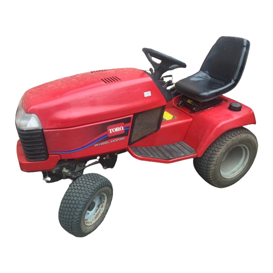
520xi Tractor
522xi Tractor
Model No. 73560 – 8900001 & UP
Model No. 73540 – 8900001 & UP
Operator's Manual
IMPORTANT: Read this manual carefully. It contains information about your
safety and the safety of others. Also become familiar with the controls and
their proper use before you operate the product.
Wheel Horse
FORM NO. 3319–215
Advertisement
Table of Contents


Need help?
Do you have a question about the Wheel Horse 73560 and is the answer not in the manual?
Questions and answers
Followed the starting procedure but still will not start?
If a Toro with part number 73560 won't start, follow these troubleshooting steps:
1. Ensure correct starting procedure is followed.
2. Check if the fuel tank is empty; if so, fill with fresh fuel.
3. Verify that the fuel shut-off valve is open.
4. Drain and flush the fuel system if dirt, water, or stale fuel is present; then add fresh fuel.
5. Inspect the fuel line for clogs; clean or replace as needed.
6. Make sure the spark plug lead is connected.
7. If the kill relay is not energized, contact an Authorized Service Dealer.
8. Replace a faulty spark plug.
9. If the ignition is faulty, contact an Authorized Service Dealer.
This answer is automatically generated