Table of Contents
Advertisement
Quick Links
Advertisement
Table of Contents

Related Manuals for Toro GrandStand 72523


Summary of Contents for Toro GrandStand 72523
- Page 1 Form No. 3435-596 Rev A GrandStand ® Multi Force Mower With 52in or 60in TURBO FORCE ® Cutting Unit Model No. 72523—Serial No. 400000000 and Up Model No. 72529—Serial No. 400000000 and Up *3435-596* A Register at www.Toro.com. Original Instructions (EN)
- Page 2 Section 4442 or 4443 to use or operate the engine on additional information, contact an Authorized Service any forest-covered, brush-covered, or grass-covered Dealer or Toro Customer Service and have the model land unless the engine is equipped with a spark and serial numbers of your product ready.
-
Page 3: Table Of Contents
Contents Checking the Spark Arrester ......37 Fuel System Maintenance ........37 Draining the Fuel Tank ........37 Safety ............... 4 Removing the Fuel Tank ........38 General Safety ........... 4 Replacing the Fuel Filter ........38 Safety and Instructional Decals ......4 Electrical System Maintenance ...... -
Page 4: Safety
Safety • Keep bystanders and children out of the operating area. Do not allow children to operate the machine. Allow only people who are responsible, trained, This machine has been designed in accordance with familiar with the instructions, and physically ANSI B71.4-2017. - Page 5 Decal 112-3858 is for 60in machines only. decal112-3858 112-3858 1. Read the Operator's 3. Remove the key before Manual. adjusting the height of cut. 2. Read the Operator's 4. Height-of-cut settings Manual before performing maintenance. decal131-1180 131-1180 1. Read the Operator's 3.
- Page 6 decal131-3521 131-3521 1. Height of cut decal131-3536 131-3536 1. Battery 4. Parking brake 2. Time 5. Engine—start 3. Power takeoff (PTO) 6. Engage the handle bars. decal133-4604 133-4604 1. Thrown object 3. Severing hazard of hand hazard—keep bystanders or foot—keep away from away from the machine.
- Page 7 decal133-8062 133-8062 decal133-4648 133-4648 1. Read the Operator's Manual for more information on servicing the machine. decal131-3526 131-3526 1. Power takeoff (PTO)—disengaged 5. Reverse 2. Fast 6. Traction drive 3. Slow 7. Engage the handles. 4. Neutral decal139-2878 139-2878 1. Warning—read the Operator’s Manual. 6.
- Page 8 decal140-4260 140-4260 1. Parking brake—disengaged 5. Fast 2. Parking brake—engaged 6. Engine speed 3. On 7. Slow 4. Off...
-
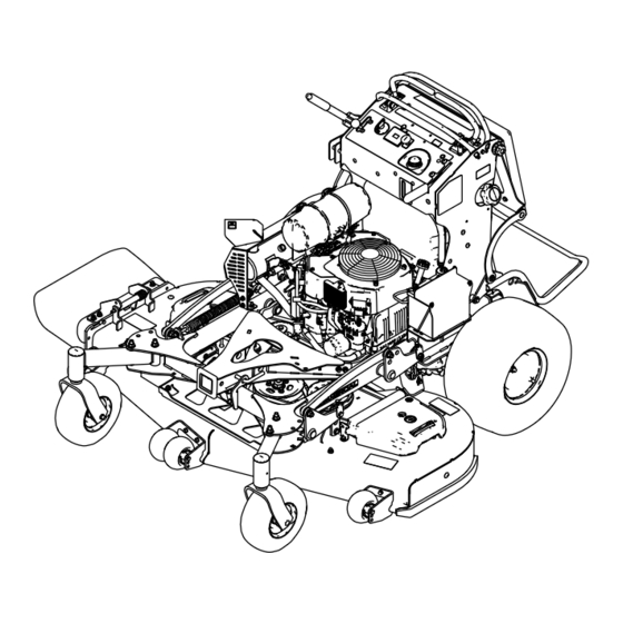
Page 9: Product Overview
Controls Product Overview Become familiar with all the controls before you start the engine and operate the machine (Figure Control Panel g306613 Figure 3 1. Adjustable caster 9. Motion-control levers 2. Accessory-frame lock 10. Hydraulic tank 3. Anti-scalp roller (60-inch 11. - Page 10 Use these times for scheduling regular Valve (page 23). maintenance (Figure Accessory Frame Use the accessory frame to attach only Toro-approved accessories to the machine (Figure 3). Refer to the Operator’s Manual for the accessory for installation instructions.
-
Page 11: Specifications
Before mowing, always inspect the machine to your Authorized Service Dealer or authorized Toro ensure that the blades, blade bolts, and cutting distributor or go to www.Toro.com for a list of all assemblies are in good working condition. approved attachments and accessories. -
Page 12: Adding Fuel
• – Store fuel in an approved container and keep Do not store fuel either in the fuel tank or fuel it out of the reach of children. containers over the winter unless you use a fuel stabilizer. • Fuel is harmful or fatal if swallowed. Long-term exposure to vapors can cause serious injury and •... -
Page 13: Performing Daily Maintenance
Performing Daily Maintenance Before starting the machine each day, perform the Each Use/Daily procedures listed in Maintenance (page 26). Breaking in a New Machine New engines take time to develop full power. Mower g031282 decks and drive systems have higher friction when Figure 8 new, placing additional load on the engine. -
Page 14: During Operation
Avoid mowing in • Use only accessories and attachments approved wet conditions. by The Toro® Company. • Before you start the engine, ensure that all drives are in neutral, the parking brake is engaged, and Slope Safety you are in the operating position. -
Page 15: Operating The Parking Brake
operation. Use common sense and good judgment when performing this evaluation. Changes in the terrain, such as moisture, can quickly affect the operation of the machine on a slope. • Operate across slopes, never up and down. Avoid operation on excessively steep or wet slopes. •... -
Page 16: Operating The Throttle
Disengaging the Power-Takeoff Operating the Throttle (PTO) Switch You can move the throttle control between F positions (Figure 13). Figure 11 Figure 12 show 2 ways to disengage the PTO. Always use the F position when engaging the PTO. g008946 Figure 13 g301401 Figure 11... -
Page 17: Starting The Engine
Starting the Engine Shutting Off the Engine Important: Do not engage the starter for more CAUTION than 5 seconds at a time. If the engine fails to start, wait 15 seconds between attempts. Failure Children or bystanders may be injured if they to follow these instructions can burn out the move or attempt to operate the machine while starter motor. -
Page 18: Operating The Platform
Operating the Platform You can use the machine with the platform in the up or down position. It is your preference on which position to use. WARNING The operator platform is heavy and may cause injury when you raise or lower it. Carefully lower or raise the operator platform, as suddenly dropping it could injure you. - Page 19 Driving Forward Disengage the parking brake; refer to Operating the Parking Brake (page 15). Move the motion-control levers to the center, unlocked position. g009473 Figure 20 Driving Backward g030983 Figure 19 Move both motion-control levers to the center, 1. Front reference bar 4.
-
Page 20: Side Discharging Or Mulching The Grass
Side Discharging or Adjusting the Height-of-Cut Mulching the Grass The height-of-cut can be adjusted from 38 to 127 mm (1-1/2 to 5 inches) in 6 mm (1/4 inch) increments. This machine has a hinged grass deflector that Note: Using a height-of-cut under 51 mm (2 inches) disperses clippings to the side and down toward the increases the wear on the mower-deck belt. -
Page 21: Adjusting The Anti-Scalp Rollers
Adjusting the Anti-Scalp Rollers Models with a 60-Inch Deck Only Whenever you change the height-of-cut, adjust the height of the anti-scalp rollers. Disengage the blade-control switch (PTO), move the motion-control levers to the N EUTRAL LOCK position, and engage the parking brake. Shut off the engine, remove the key, and wait for all moving parts to stop before leaving the operating position. -
Page 22: Using Weights
Position B Using Weights Use this position when bagging (Figure 26). • Install weights to improve balance. You can add or remove weights to create optimized performance under different operating conditions and for your preference. • Add or remove weights 1 at a time until you achieve the desired handling and balance. -
Page 23: Preventing Freeze-Up After Use
Preventing Freeze-up after Pushing the Machine by Hand • In snowy and cold conditions, some controls and The bypass valves allow you to push the machine by moving parts may freeze. Do not use excessive hand without the engine running. force when trying to operate frozen controls. -
Page 24: Transporting The Machine
Transporting the Machine Use a heavy-duty trailer or truck to transport the machine. Use a full-width ramp. Ensure that the trailer or truck has all the necessary brakes, lighting, and marking as required by law. Please carefully read all the safety instructions. Knowing this information could help you or bystanders avoid injury. - Page 25 g031405 Figure 31 1. Back the machine up the 2. Walk the machine down ramp. the ramp. Shut off the engine, remove the key, and engage the parking brake. Tie down the machine near the front caster wheels and the rear bumper with straps, chains, cable, or ropes (Figure 32).
-
Page 26: Maintenance
To ensure optimum performance and continued the engine running. safety certification of the machine, use only • Carefully release pressure from components with genuine Toro replacement parts and accessories. stored energy. Replacement parts and accessories made by • Check the parking brake operation frequently. -
Page 27: Pre-Maintenance Procedures
Maintenance Service Maintenance Procedure Interval • Change the engine oil. • Check the battery. • Check the clutch. Every 100 hours • Check and clean the engine cooling fins and shrouds (more often in dirty or dusty conditions). • Check the mower-deck belt(s). •... -
Page 28: Lubrication
Lubrication Greasing the Torsion Idler Service Interval: Yearly Greasing the Machine Grease the torsion idler on the mower deck using high-temperature grease at the grease fitting shown Grease with No. 2 lithium or molybdenum grease. Figure Disengage the PTO and set the parking brake. Important: Use only high-temperature grease. -
Page 29: Greasing The Caster-Wheel Hubs
Greasing the Caster-Wheel Insert the assembled nut and axle into the wheel on the side of the wheel with the new seal and Hubs bearing. With the open end of the wheel facing up, fill Service Interval: Yearly the area inside the wheel around the axle full of Grease type: Lithium or molybdenum grease general-purpose grease. -
Page 30: Greasing The Brake Calipers
Greasing the Motion Controls Service Interval: Yearly Grease the operator-presence-control balljoint and the motion-control bushing for both levers. Note: Use an oil drip between the lever brackets to grease the bushing, located in the pivot tube. g228035 Figure 37 1. Voltage regulator 2. -
Page 31: Engine Maintenance
Engine Maintenance Engine Safety • Shut off the engine before checking the oil or adding oil to the crankcase. • Keep your hands, feet, face, clothing, and other body parts away from the muffler and other hot surfaces. Servicing the Air Cleaner g012996 Figure 40 Service Interval: Every 150 hours... -
Page 32: Servicing The Engine Oil
Inspecting the Filters Servicing the Engine Oil Inspect the safety filter. If it is dirty, replace both the safety and primary filters. Engine-Oil Specifications Important: Do not attempt to clean the Oil Type: Detergent oil (API service SJ or higher) safety filter. - Page 33 Checking the Engine-Oil Level Service Interval: Before each use or daily Note: Check the oil when the engine is cold. WARNING Contact with hot surfaces may cause personal g032691 injury. Keep your hands, feet, face, clothing and other body parts away the muffler and other hot surfaces.
- Page 34 Changing the Engine Oil Service Interval: After the first 8 hours Every 100 hours Note: Dispose of the used oil at a recycling center. Park the machine so that the drain side is slightly lower than the opposite side to assure the oil g032710 drains completely.
- Page 35 Changing the Engine-Oil Filter Service Interval: Every 200 hours Note: Change the engine-oil filter more frequently when operating conditions are extremely dusty or sandy. Drain the oil from the engine; refer to Changing the Engine Oil (page 34). Change the engine-oil filter (Figure 46).
-
Page 36: Servicing The Spark Plug
Servicing the Spark Plug Checking the Spark Plug Important: Do not clean the spark plug(s). Service Interval: Every 200 hours Always replace the spark plug(s) when it has a Make sure that the air gap between the center and black coating, worn electrodes, an oily film, or side electrodes is correct before installing the spark cracks. -
Page 37: Checking The Spark Arrester
Checking the Spark Fuel System Arrester Maintenance For Machines with a Spark Draining the Fuel Tank Arrester You can drain the fuel tank by removing it and pouring Service Interval: Every 50 hours the fuel out of the fill neck; refer to Removing the Fuel Tank (page 38). -
Page 38: Removing The Fuel Tank
Removing the Fuel Tank Replacing the Fuel Filter Lower the platform. Service Interval: Every 800 hours/Yearly (whichever comes first) Release the cushion; refer to Releasing the Cushion for Rear Access (page 27). Do not install a dirty filter if it is removed from the fuel line. -
Page 39: Electrical System Maintenance
Electrical System Maintenance Electrical System Safety • Disconnect the battery or remove the spark-plug wire before making any repairs. Disconnect the negative terminal first and the positive terminal last. Connect the positive terminal first and negative last. • Charge the battery in an open, well-ventilated area, away from sparks and flames. - Page 40 Charging the Battery Installing the Battery Install the battery as shown in Figure WARNING Charging the battery produces gasses that can explode. Never smoke near the battery and keep sparks and flames away from battery. Important: Always keep the battery fully charged (1.265 specific gravity) to prevent battery damage when the temperature is below 0°C (32°F).
-
Page 41: Servicing The Fuses
Servicing the Fuses Drive System Maintenance The electrical system is protected by fuses. It requires no maintenance. If a fuse blows, check the component or circuit for a malfunction or short. Adjusting the Tracking Park the machine on a level surface, disengage the PTO, and engage the parking brake. -
Page 42: Checking The Tire Pressure
Adjusting the Caster-Pivot Check for proper tracking, and adjust the rod as necessary. Bearing Note: If you are unable to achieve proper tracking by adjusting the left control rod, contact Service Interval: Every 500 hours/Yearly (whichever your Authorized Service Dealer. comes first) Check that the machine does not creep from Disengage the blade-control switch (PTO), move... -
Page 43: Servicing The Caster Wheels And Bearings
Servicing the Caster Tighten the locknut until the spanner bushing bottoms against the inside of the caster forks Wheels and Bearings (Figure 60). Grease the fitting on the caster wheel. The caster wheels rotate on a roller bearing supported by a spanner bushing. If the bearing is kept well lubricated, wear will be minimal. - Page 44 Check the condition of the wire-harness leads, Using a 0.010 inch thick-feeler gauge, verify connectors, and terminals. Clean or repair them that a gap is present between the rotor and as necessary. armature face on both sides of the brake pole as shown in Figure 65 Figure...
-
Page 45: Checking The Wheel-Lug Nuts
Cooling System Perform the following safety check: Start the engine from the operator’s Maintenance position. Make sure that the blades do not engage when the PTO switch is in Cleaning the Air-Intake the O position and the clutch is Screen disengaged. -
Page 46: Brake Maintenance
Brake Maintenance Belt Maintenance Testing the Parking Brake Checking the Belts Service Interval: Before each use or daily Service Interval: Every 100 hours—Check the mower-deck belt(s). Before each use, test the parking brake on both a level surface and slope. Check belts for cracks, frayed edges, burn marks, wear, signs of overheating, or any other damage. -
Page 47: Replacing The Transmission Belt
Replacing the Transmission Belt Service Interval: Every 1,000 hours—Replace the transmission belt. Remove the fuel tank; refer to Removing the Fuel Tank (page 38). Remove the hydraulic-reservoir cap. Locate the drain plugs in the bottom of the transmission and place a drain pan under the plug (Figure 70). -
Page 48: Controls System Maintenance
Controls System CAUTION The spring is under tension when Maintenance installed and can cause personal injury. Wear safety glasses and be careful when Adjusting the removing the spring. Motion-Control Levers Remove the deck belt from the clutch and clutch stop (Figure 71). -
Page 49: Hydraulic System Maintenance
Hydraulic System Important: Ensure that the flat portion of the cam does not go above a vertical position Specifications (right or left); otherwise you may damage the switch. Hydraulic Fluid Type: Toro ® HYPR-OIL ™ Repeat steps through for the left hydraulic fluid motion-control lever. -
Page 50: Replacing The Hydraulic Fluid And Filters
Remove the hydraulic-reservoir cap. Locate the drain plug in the bottom of each transmission and place a drain pan under the plugs (Figure 75). g301336 Figure 74 g268090 Figure 75 1. Hydraulic-tank cap 2. Cold fluid level 1. Drain plug 2. -
Page 51: Bleeding The Hydraulic System
Mower Deck Important: Use the fluid specified in Hydraulic System Specifications (page 49) Maintenance equivalent. Other fluids could cause system damage. Important: Monitor the level of fluid in the Blade Safety hydraulic tank so that you do not overfill it. Tighten the vent plugs. - Page 52 WARNING A blade that is bent or damaged could break apart and could critically injure you or bystanders. • Always replace a bent or damaged blade with a new blade. • Do not file or create sharp notches in the edges or surfaces of the blade. g006530 Figure 77 Removing the Blades...
-
Page 53: Removing The Mower Deck
g000552 Figure 80 1. Sharpen at original angle. Check the balance of the blade by putting it on a blade balancer (Figure 81). Note: If the blade stays in a horizontal position, the blade is balanced and can be used. Note: If the blade is not balanced, file some metal off the end of the sail area only... - Page 54 g033736 Figure 84 Right side shown g033738 Figure 86 1. Bolt 3. Nut Left Side of 60-inch Deck Shown 2. Strut bracket 1. Bolt 4. Lift plate 2. Washer 5. Mower-deck hanger Remove the 2 bolts, 2 nuts, and washer connecting the mower-deck hangers to the lift 3.
-
Page 55: Installing The Mower Deck
Preparing the Machine shaft, then install the bolt, washer, spring Ensure that the mower deck is level any time you washer, and a spacer (Toro part no. install the mower deck or when you see an uneven 136-5411) to the shaft (Figure 88). - Page 56 Note: If it is not correct, refer to Leveling the Mower Deck from Side to Side (page 56). Leveling the Mower Deck from Side to Side Loosen the side nut and jam nut in the yokes you want to adjust (Figure 90).
-
Page 57: Adjusting The Deck-Lift Spring
Adjusting the Deck-Lift Note: Rotate the bolt clockwise to raise the deck; rotate the bolt counterclockwise to lower it. Spring Tighten the jam nuts and side bolts. Note: Adjusting the compression spring alters how Check the front-to-rear pitch; refer to Checking much the deck floats and the amount of effort needed the Mower Deck Front-to-Rear Pitch (page... -
Page 58: Replacing The Grass Deflector
Replacing the Grass Cleaning Deflector Cleaning under the Mower WARNING Deck An uncovered discharge opening could allow the machine to throw objects toward you or Service Interval: Before each use or daily bystanders, resulting in serious injury. Also, Before each use or daily contact with the blade could occur. -
Page 59: Storage
Storage Dispose of fuel properly; recycle it according to local regulations. Important: Do not store fuel containing Storage Safety stabilizer/conditioner longer than the duration recommended by the • Let the engine cool before storing the machine. fuel-stabilizer manufacturer. • Do not store the machine or fuel near flames or Remove the spark plug(s) and check its drain the fuel indoors. -
Page 60: Troubleshooting
Troubleshooting Problem Possible Cause Corrective Action The engine does not start, starts hard, or 1. The fuel tank is empty or the shutoff 1. Fill the fuel tank with fuel and open the fails to keep running. valve is closed. valve 2. - Page 61 Problem Possible Cause Corrective Action The cutting height is uneven. 1. Blade(s) are not sharp. 1. Sharpen the blade(s). 2. Cutting blade(s) is/are bent. 2. Install new cutting blade(s). 3. The mower deck is not level. 3. Level the mower deck side-to-side position.
-
Page 62: Schematics
Schematics g301844 Electrical Schematic—138-8898 (Rev. B) - Page 63 Notes:...
- Page 64 While the exposure from Toro products may be negligible or well within the “no significant risk” range, out of an abundance of caution, Toro has elected to provide the Prop 65 warnings. Moreover, if Toro does not provide these warnings, it could be sued by the State of California or by private parties seeking to enforce Prop 65 and subject to substantial penalties.
Need help?
Do you have a question about the GrandStand 72523 and is the answer not in the manual?
Questions and answers