
Related Manuals for Solo 2625 01i neo

Summary of Contents for Solo 2625 01i neo
- Page 1 Service-manual For the aircraft engines 2625 01i neo and 2625 02i neo SOLO Kleinmotoren GmbH Stuttgarter Str. 41 D - 71069 Sindelfingen Tel.: (0049) 7031-3010 Fax.: (0049) 7031-301231 Edition 1 dated 26.11.2020...
-
Page 2: Table Of Contents
SOLO 2625 01i neo Service Manual KLEINMOTOREN 2625 02i neo GMBH Table of contents General hints and description of the engines ............3 Description ............Fehler! Textmarke nicht definiert. Basics ............Fehler! Textmarke nicht definiert. Engine electrics overview ................... 4 2.2.1... - Page 3 This service-manual is valid together with the engine-manual and the spare-parts-list. General knowledge of two-stroke-engines is required to work on SOLO-aircraft-engines. ! Attention ! Because this engine is used as a certified engine for motor gliders, the national authorizations of the specific certifying staff must be maintained.
-
Page 4: Description
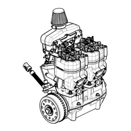
2 Description 2.1 Basics The aircraft engines SOLO 2625 01i neo and 02i neo are water cooled two cylinder two- stroke engines with piston-ports and map-controlled intake-manifold fuel injection and ignition. They are lubricated by a fuel-oil-mixture. They are based on the 2625 01i or 2625 02i. -
Page 5: Working Method Of The Engine Control Unit (Ecu)
CAN. The former allows a computer to be connected to check the status of the engine control unit or read the error memory using the WinTrijekt NEO software, which can be downloaded from the SOLO website https://aircraft.solo.global/de/. Both engine operation data and fault messages can be transmitted via the CAN interface, for example to display them on an engine operation unit. -
Page 6: Wire Diagrams Electrics
SOLO 2625 01i neo Service Manual KLEINMOTOREN 2625 02i neo GMBH 2.2.2 Wire diagrams electrics Wire diagram control unit Verteilerleiste Leistungsmasse Verteilerleiste +12V Sicherung FP 1 5A M Sicherung FP 2 5A M Schalter Zündkreis 2 Schalter Zündkreis 1 Zylinder 1... - Page 7 SOLO 2625 01i neo Service Manual KLEINMOTOREN 2625 02i neo GMBH Wire diagram power supply Wire diagram fuel pump electronic unit a) with signal and power supply connector Strom- versorgungs- Signalstecker stecker (Deutsch DTM04-6P) (Deutsch DTM04-4P) 1 2 3 4 5 1 2 3 4 470 Ω, 1W...
-
Page 8: Fuel Supply System
2.3.1 Fuel line diagram The following fuel line diagram shows the fuel system when using the SOLO fuel supply unit (BVE), but without the required tank inlet filter(s). If other fuel pumps are installed, deviations may occur. These are then at the discretion and responsibility of the aircraft manufacturer. -
Page 9: Redundancy Functions
SOLO 2625 01i neo Service Manual KLEINMOTOREN 2625 02i neo GMBH 2.4 Redundancy functions In order to ensure a high degree of operational safety, almost all electrical components essential for engine operation are redundant (see 2.3). The exception is the ECU itself, where redundant electronics have been omitted due to its high reliability. - Page 10 SOLO 2625 01i neo Service Manual KLEINMOTOREN 2625 02i neo GMBH Component(s) Automatic Error detection, ECU reaction monitoring by the and effects of errors Fuel pumps While the fuel Both fuel pumps are operated in parallel and pumps are on (for monitored by their power consumption.
-
Page 11: Inspections And Maintenance Intervals
SOLO 2625 01i neo Service Manual KLEINMOTOREN 2625 02i neo GMBH 3 Inspections and maintenance intervals Daily pre-flight check Before starting the engine: − Check fuel supply. − Check the movement of the throttle lever. − Check the external condition of the engine and belt transmission. -
Page 12: Disassembly, Check And Assembly
3 pcs. 00 10 150 Cylinder screw M 8 x 40 00 80 314 Pressure tester Two-stroke oil Castrol Power 1 Racing 2T, SOLO two- stroke oil or other oils with specification JASO FC or FD 00 83 177 Air filter oil... -
Page 13: Engine
Allen key 6 mm residues and oil. Loosen the fastening of the generator rotor and Puller SOLO-No. 00 80 530 pull off the rotor with a suitable puller. Remove the stator of the generator completely and unscrew the mounting plate. -
Page 14: Check Of The Individual Parts
SOLO 2625 01i neo Service Manual KLEINMOTOREN 2625 02i neo GMBH 4.3.2 Check of the individual parts Cylinder heads − Carefully remove adhering combustion residues. Fuel can dissolve oil residues. Scrape off stubborn oil carbon residues with a steel brush. - Page 15 SOLO 2625 01i neo Service Manual KLEINMOTOREN 2625 02i neo GMBH Crankshaft The crankshaft can only be disassembled by the manufacturer. However, the main bearings (roller bearings) on the output side and on the ignition or generator side can be replaced.
-
Page 16: Assembly Of The Engine
SOLO 2625 01i neo Service Manual KLEINMOTOREN 2625 02i neo GMBH 4.3.3 Assembly of the engine The bearings of the crankshaft, as well as piston pin bearings and pistons must be lubricated with two-stroke oil during assembly. Operation Tool, aid Heat the inner rings of the roller bearings to 180°C and... -
Page 17: Throttle Valve System 23 00 891 V1/V2
SOLO 2625 01i neo Service Manual KLEINMOTOREN 2625 02i neo GMBH 4.4 Throttle valve system 23 00 891 V1/V2 4.4.1 Hints for disassembly − The throttle valve screws are caulked and must therefore be drilled out. − The sensor guide bush is best removed by hand using an M12 tap. -
Page 18: Rpm Sensor
SOLO 2625 01i neo Service Manual KLEINMOTOREN 2625 02i neo GMBH − Note: The holes in the sheet metal parts may be drilled out if necessary: Through-holes M4 screws: max. 4.9mm, Through-holes M5 screws: max. 5.8mm. − Thread lockage: o All M4 / M5 screws and the plug screws must be secured with Loctite 243. -
Page 19: Hints For Disassembly
SOLO 2625 01i neo Service Manual KLEINMOTOREN 2625 02i neo GMBH 4.6 Fuel supply system 4.6.1 Hints for disassembly − The fuel pumps must be removed before the check valves can be unscrewed with an Allen key 5mm. − Attention! The spring which holds the fuel filter is tensioned. -
Page 20: Basics
SOLO 2625 01i neo Service Manual KLEINMOTOREN 2625 02i neo GMBH 5 Diagnosis and elimination of engine malfunctions 5.1 Basics 5.1.1 Handling with WinTrijekt NEO To check the status of the ECU or to read the error memory, a computer with WinTrijekt and a serial connection cable (RS 232) are required. - Page 21 SOLO 2625 01i neo Service Manual KLEINMOTOREN 2625 02i neo GMBH b) Sensors Note: If disturbances of the sensors occur only rarely and for a short time (for a few ms), this is usually not critical. No reaction is then required. In particular, individual speed errors when starting or stopping the engine are normal and no cause for concern.
-
Page 22: Check The Status Of The Engine
SOLO 2625 01i neo Service Manual KLEINMOTOREN 2625 02i neo GMBH 5.3 Check the status of the engine Directly after starting WinTrijekt NEO the status window opens automatically. There, a lot of helpful information is displayed when the engine control unit is switched on and... -
Page 23: Special Cases
SOLO 2625 01i neo Service Manual KLEINMOTOREN 2625 02i neo GMBH 5.4 Special cases 5.4.1 Engine will not start 1. Check battery voltage. 2. Check fuel supply. 3. Check if the ECU is supplied with voltage. 4. Ignition off! Crank engine by hand and check compression. - Page 24 SOLO 2625 01i neo Service Manual KLEINMOTOREN 2625 02i neo GMBH 6 Notes Edition 1 dated 26.11.2020 page 24...
Need help?
Do you have a question about the 2625 01i neo and is the answer not in the manual?
Questions and answers