Subscribe to Our Youtube Channel
Summary of Contents for POD Point Solo 3 - Commercial
- Page 1 Fast Charging Solo 3 - Commercial Install Guide Solo 3 - Commercial PP-D-210451-3 Install Guide (No Dip Switches)
-
Page 2: Install Location
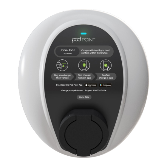
Solo 3 - Commercial This document details the installation guidance for the Solo 3 (Commercial) variant of the Solo 3 product family. If you’re unsure which model you are planning to install, please contact your account manager or Pod Point directly. - Page 3 Technical details RCD protection: The Solo 3 is a Class I/II rated device, pollution All Pod Point Solo 3s include 6mA DC vehicle degree 3 for 230V / 400V AC 50Hz systems fault protection and only Type A RCD/RCBOs and is IP54 and IK10 rated.
- Page 4 Solo 3 - Commercial Transformers nstallation procedure If a galvanically isolated transformer is required, Please note: it should be placed upstream of the EVSE. The The information in this section is advice ● neutral output feed of the transformer should be...
- Page 5 Solo 3 - Commercial Drilling template (box insert) Fig. 4 - Drilling the holes for the electrical supply cable entry The Solo 3 has been designed to accept supply cable entry on either the left, right, bottom or via the rear. Top entry is only possible if there is no risk of water ingress (indoor).
- Page 6 Solo 3 Supply Wiring Wiring of Array Controller. When included as part of an Array system (multiple NOTE: There are variations of the Pod Point chargers connected to the same power supply) the EVSE main PCBA. Check markings at the...
- Page 7 Only the the page 192.168.101.1 or remotely when domestic and Solo 3 “loads” should be connected to Wi-Fi by contacting Pod Point measured by the CT. customer support to change this value. Where the only available supply cable includes Wiring of the Energy Clamp PV or storage “export”...
- Page 8 Solo 3 - Commercial Setting up the Solo 3 Never use IDC terminals for the installation Current rating, cable overcurrent protection and load If a consumer unit includes a spare non-RCD curtailment settings must be set before testing and protected circuit, this may be used to supply the final assembly of the unit.
- Page 9 ● Confirm the new circuit insulation resistance. from the connector on the PC ● Confirm the polarity of the installation is 2. Plug the Pod Point EV simulator into the Solo correct. 3 and the heater into the EV simulator socket.
- Page 10 Pod Point App. In exceptional circumstances Pod Point may contact the site/charger owner if an abnormality is detected.
- Page 11 Solo 3 using the MAC address may be the only option. The MAC address can be provided To commission a commercial Pod by Pod Point from the PSL number of the unit Point charger you will need to which can then be included in the router’s complete the commission form allowlist.
- Page 12 This will prevent customers, including how to connect the Solo 3 activation of the tamper detection which will to Wi-Fi, how to commission Pod Point prohibit further testing and be visible by the chargepoints, and various troubleshooting presence flashing...


Need help?
Do you have a question about the Solo 3 - Commercial and is the answer not in the manual?
Questions and answers