
Related Manuals for MRC SRI3P-2


Summary of Contents for MRC SRI3P-2
- Page 1 Installation - Operation Manual BOD INCUBATORS SRI3P/6P/20P-2 3, Hagavish st. Israel 58817 Tel: 972 3 5595252, Fax: 972 3 5594529 mrc@mrclab.com MRC. 6.23...
- Page 2 Not for Fly Cultivation This unit is not designed to hold fruit flies (Drosophila melanogaster). Use with flies voids the manufacturing warranty and risks damaging the unit. Other incubator models in the SRIP family are specifically manufactured for fly applications. Talk to your distributor or customer service representative to identify a model compatible with your study or production model.
- Page 3 Refrigerated BOD Incubators 100 – 120 Voltage Models: SRI3, SRI6P, SRI20P 220 – 240 Voltage Models: SRI3P-2, SRI6P-2, SRI20P-2 Part Number (Manual) 4861666-1 Revision: October 4, 2021 P a g e...
-
Page 4: Table Of Contents
TABLE OF CONTENTS MODEL CERTIFICATIONS ............................7 Electromechanical Safety Testing ............................. 7 CE Compliant ................................... 7 UKCA Compliant ..................................7 ISO Certified Manufacturer ..............................8 INTRODUCTION ................................ 9 Read this Manual ..................................9 Safety Considerations and Requirements ........................9 Contacting Assistance ................................ 10 Manufacturing Warranty .............................. - Page 5 Power ...................................... 54 Temperature ..................................55 PARTS LIST ................................57 P a g e...
- Page 6 TABLE OF CONTENTS P a g e...
-
Page 7: Model Certifications
MODEL CERTIFICATIONS Model Certification and Compliance Statements LECTROMECHANICAL AND EATING AFETY IEC 61010-1:2010, AMD1:2016 and 61010-2-010:2019 Safety Certified + USA, Canada, Europe Differences These unit models are certified by Intertek as compliant with the International Electrotechnical Commission’s 61010 safety standards for electrical and mechanical hazards as well as the heating of materials in laboratory devices. -
Page 8: Iso Certified Manufacturer
CERTIFICATIONS ISO C ERTIFIED ANUFACTURER We are a brand of our Manufacturing, INC, an ISO 9001 certified manufacturer P a g e... -
Page 9: Introduction
INTRODUCTION Thank you for purchasing the incubator. We know you have many choices in today’s competitive marketplace when it comes to constant temperature equipment. We appreciate you choosing ours. We stand behind our products and will be here if you need us EAD THIS ANUAL Failure to follow the guidelines and instructions in this user manual may create a protection impairment... -
Page 10: Contacting Assistance
INTRODUCTION ONTACTING SSISTANCE Phone hours for Customer Support are Hagavish st. Israel 58817 Tel: 972 3 5595252, Fax: 972 3 5594529 mrc@mrclab.com ,3 ANUFACTURING ARRANTY For information on your warranty and online warranty registration please visit NGINEERING MPROVEMENTS Our Manufacturing continually improves all of its products. As a result, engineering changes and improvements are made from time to time. -
Page 11: Reference Sensor Device
INTRODUCTION EFERENCE ENSOR EVICE Must be purchased separately Temperature Reference Temperature Calibrations If you are not using a third-party service, a reference sensor device is required for calibrating your unit’s temperature display. See the Calibrating the Temperature Display procedure on page 49 for more information. •... - Page 12 INTRODUCTION 12 | P a g e...
-
Page 13: Receiving Your Unit
RECEIVING YOUR UNIT NSPECT THE HIPMENT When a unit leaves the factory, safe delivery becomes the responsibility of the carrier. • Damage sustained during transit is not covered by the manufacturing defect warranty. • Save the shipping carton until you are certain that the unit and its accessories function •... -
Page 14: Orientation Images
RECEIVING RIENTATION MAGES Peltier Thermoelectric Heater – Chiller Housing Control Panel SRI20P Access Port Drain Port - TEC Housing Shelf Mounting Bracket SRI20P Chamber Power Outlet, NEMA 5-15R 100 – 120 Volt* Shelf Standard Rail Humidification Pan Door Gasket Chamber Door *SRI20P-2 Chamber Power Outlet, CEE7/3 220 –... - Page 15 RECEIVING SRI6P Control Panel Peltier Thermoelectric Heater – Chiller Housing Drain Port - TEC Housing SRI6P Chamber Power Outlet, NEMA 5-15R 100 – 120 Volt* Access Port Humidification Pan Door Gasket Chamber Door *SRI6P-2 Chamber Power Outlet, CEE7/3 220 – 240 Volt 15 | P a g e...
- Page 16 RECEIVING Data Plate Power Panel Chamber Access Port Second Fuse Holder (220V Incubators only) Power Panel Closeup Power Cord Inlet with Fuse Holder 16 | P a g e...
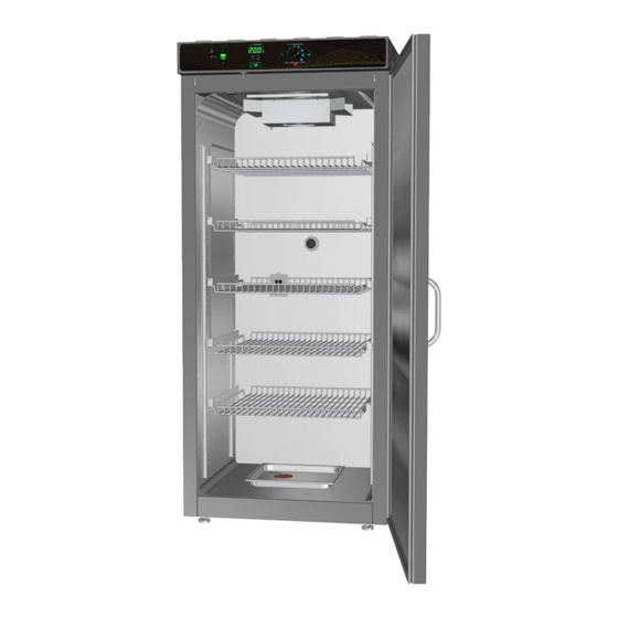
- Page 17 Drain Port - TEC Housing Control Panel Shelf Standard Rail SRI3P Chamber Power Outlet, NEMA 5-15R 100 – 120 Volt* Access Port Humidification Pan Door Gasket Chamber Door *SRI3P-2 Chamber Power Outlet, CEE7/3 220 – 240 Volt 17 | P a g e...
- Page 18 RECEIVING SRI3P, Left Side of Unit Power Cord Inlet with Fuse Second Fuse Holder (220V Incubators only) 18 | P a g e...
-
Page 19: Recording Data Plate Information
RECEIVING ECORDING LATE NFORMATION Record the unit model number, serial number, and part number below for future reference. Customer Support needs this information to provide accurate help during support calls and emails. SRI6P, SRI20P: The data plate is located on the back of the unit, above the power inlet SRI3P: The data plate is located on the left side of the unit, next to the power inlet MODEL NO: SERIAL NO:... - Page 20 RECEIVING 20 | P a g e...
-
Page 21: Installation
INSTALLATION NSTALLATION ROCEDURE HECKLIST Carry out the procedures and steps listed below to install the incubator in a new workspace location and prepare it for use. All procedures are found in the Installation section of this manual. Pre-Installation Check that the required ambient condition for the unit are met, page 22 ... -
Page 22: Required Ambient Conditions
INSTALLATION EQUIRED MBIENT ONDITIONS Ambient Temperature Ranges: These units are built for use indoors under climate-controlled conditions of 15.0°C to 30.0°C (59.0°F to 86.0°F). SRIP3s In workspace temperatures of 15.0°C to 30.0°C (59.0°F to 86.0°F), the SRI3P incubators can • achieve an operational chamber temperature range of 15.0°C to 40.0°C. -
Page 23: Required Clearances
INSTALLATION EQUIRED LEARANCES These clearances are required to provide airflows for ventilation and cooling. 2” (51 mm) 2” (51 mm) Power Cord Access Port 4” (102 mm) 4” (102 mm) 4” (102 mm) Door Swing SRI3P: 24.5” (623 mm) SRI6P 30.5” (775 mm) (SRI20P 30.5”... -
Page 24: 110 - 120 Volt Power Source Requirements
INSTALLATION Note: See the next page for the -2, 220-volt incubators. 100 – 120 V OWER EQUIREMENTS Applies to: SRI3P, SRI6P, SRI20P When selecting a location for the unit, verify each of the following requirements is satisfied. Power Source: The power source for the unit must match the voltage and match or exceed the ampere requirements listed on the unit data plate. -
Page 25: 220 - 240 Volt Power Source Requirements
OWER OURCE EQUIREMENTS Applies to: SRI3P-2, SRI6P-2, SRI20P-2 When selecting a location for the unit, verify each of the following requirements is satisfied. Power Source: The power source for the unit must match the voltage and match or exceed the ampere requirements listed on the unit data plate. -
Page 26: Lifting And Handling
INSTALLATION IFTING AND ANDLING The unit is heavy. Use appropriate lifting devices that are sufficiently rated for these loads. Follow these guidelines when lifting the unit. Lift the unit only from its bottom surface. • Doors, handles, and knobs are not adequate for lifting or stabilization. •... -
Page 27: Install The Incubator
INSTALLATION NSTALL THE NCUBATOR Install the unit in a workspace location that meets the criteria discussed in the previous entries of the Installation chapter. EIONIZED AND ISTILLED ATER Do not use deionized water to clean the unit, even if DI water is readily available in your laboratory. The use of deionized water may corrode metal surfaces and voids the manufacturing •... -
Page 28: Install The Sri20P Side Air Ducts
INSTALLATION SRI20P S NSTALL THE UCTS Two air duct panels are packed with the accessories of the SRI20P incubators. Installation Insert the panel hooks, facing down, into the large notches in the shelf standard mounting rails. SRI3P and SRI6P incubators do not use Side Air Ducts. Note: The air duct panels play an important role in maintaining even air distribution inside the SRI20P incubation chamber. -
Page 29: Shelving Installation
INSTALLATION HELVING NSTALLATION SRI3P Shelf Installation Perform the following steps to install the wire basket shelves of the SRI3P incubator: Install the shelf clips in the slots located on the shelf standards (mounting rails) of the chamber interior, both front and back. a. - Page 30 INSTALLATION Shelving Installation Continued SRI6P and SRI20P Static Shelves Remove all protective wrappings from shelves and shelving components prior to installation. Standard Shelf Bracket Installation Standard Bracket Installed Shelf hung from mounting bracket Insert the twin tabs on the bracket into slots in the shelf standard mounting rails located on the sides of the incubation chamber.
- Page 31 INSTALLATION Shelving Installation Continued Sliding Shelf Installation SRI20P Note: SRI6P do not come with sliding shelf brackets. Sliding brackets for SRI6P must be purchased separately 2. Slide the bracket down 1. Insert the sliding shelf mounting bracket tabs 3.2 Tighten the screws. 3.1.
-
Page 32: Access Port Stopper
INSTALLATION CCESS TOPPER Each incubator ships with a rubber stopper installed in the access port located in the back of the incubation chamber. The stopper should always be installed inside the chamber to obtain the • best temperature uniformity and prevent condensation from forming inside the port. -
Page 33: Graphic Symbols
GRAPHIC SYMBOLS The unit is provided with multiple graphic symbols on its exterior. The symbols identify hazards and the functions of the adjustable components, as well as important notes in the user manual. Symbol Definition Consult the user manual. Consulter le manuel d'utilisation Temperature display Indique l'affichage de la température Over Temperature Limit system... - Page 34 SYMBOLS 34 | P a g e...
-
Page 35: Control Panel Overview
CONTROL PANEL OVERVIEW Control Panel SRI6P SRI20P Top | SRI3P Bottom Power Switch Power is supplied and the switch illuminates when in the ( I ) ON position. Set Temperature Display and Controls Shows the current chamber temperature. The Up and Down arrow buttons are used to access the Temperature Setpoint (SP) or Calibration Offset (C O) display modes and input the temperature setpoint or calibration adjustment value and turn the door open alarm off or on. - Page 36 CONTROLS 36 | P a g e...
-
Page 37: Operation
OPERATION HEORY OF PERATION SRIP incubators provide stable and uniform incubation environments suitable for biological oxygen demand studies, including at or below standard room temperature. Heating and Cooling The incubator employs a solid-state thermoelectric cooling-and-heating (TEC-H) device, which operates using the Peltier effect to supply heating or cooling as needed. The Peltier effect: An electrical current between two touching but dissimilar conductor plates produces a heat flow from one plate to the other. - Page 38 OPERATION Door Alarm The incubator is equipped with a magnetic induction door alarm, which activates when the door is open for 60 seconds. When the alarm is active, an audio alert will sound, and the temperature display will flash. Closing the door will temporarily turn off the alarm. The alarm may be turned off indefinitely using the Door Alarm Setting procedure on page 4545...
-
Page 39: Put The Incubator Into Operation
OPERATION UT THE NCUBATOR INTO PERATION Carry out the following steps and procedures to put the unit into operation after installing it in a new workspace environment. Plug in the power cord Attach the power cord that came with the unit to the power inlet receptacle on the back of the incubator. -
Page 40: Set The Temperature Setpoint
OPERATION ET THE EMPERATURE ETPOINT Perform the steps below to adjust the setpoint to your process or application temperature. 1. Set the OTL control to its maximum setting, if not already set to max This prevents the heating cutoff system •... -
Page 41: Set The Over Temperature Limit (Otl)
OPERATION Note: Test the OTL system at least once per year to verify its functionality. Failure to set the OTL voids the manufacturing defect warranty if over temperature damage occurs. (OTL) ET THE EMPERATURE IMIT This procedure sets the mechanical heating cutoff to approximately 1˚C above the current chamber temperature. -
Page 42: Loading Samples
1 amp. The SRI3P, SRI6P, and SRI20P power outlet provides 100 – 120 volts. • The SRI3P-2, SRI6P-2, and SRI20P-2 power outlet provides 220 – 240 volts. • Verify that any powered accessory equipment used inside the chamber can safely and effectively operate within your selected temperature range. -
Page 43: Humidifying The Incubator
OPERATION UMIDIFYING THE NCUBATOR Closed bottle BOD applications do not require humidification. Breathable Sample Containers: Placing a small number of open or breathable media containers in the incubator chamber may lead to excessive drying of sample media. Unusually dry environmental conditions may also contribute to sample drying. -
Page 44: Condensation And The Dew Point
OPERATION ONDENSATION AND THE OINT Relative humidity inside the incubation chamber should never be allowed to exceed 80% at 25°C. Exceeding this threshold will likely result in condensation and leaks around the incubator and may cause corrosion damage if allowed to continue for any significant length of time. Condensation takes place whenever the humidity level in the incubation chamber reaches the dew point. - Page 45 OPERATION Note: Changing the Door Alarm setting accesses the Temperature Setpoint menu but does not adjust the temperature setpoint. LARM ETTING The incubator comes with a Door Alarm that sounds an audible alarm and causes the temperature display to blink on and off when the door has been open for longer than 60 seconds. The alarm comes from the factory set to On.
- Page 46 OPERATION 46 | P a g e...
-
Page 47: User Maintenance
USER MAINTENANCE Warning: Disconnect this unit from its power supply prior to performing maintenance or services. Avertissement: Débranchez cet appareil de son alimentation électrique avant d'effectuer la maintenance ou les services. LEANING AND ISINFECTING If a hazardous material or substance has spilled in the unit chamber, immediately initiate your site Hazardous Material Spill Containment protocol. -
Page 48: Door Components
MAINTENANCE Disinfecting For maximum effectiveness, disinfection procedures are typically performed after cleaning. Keep the following points in mind when disinfecting the unit. Turn off and disconnect the unit to safeguard against electrical hazards. • Disinfect the unit chamber using commercially available disinfectants that are non-corrosive, •... -
Page 49: Calibrate The Temperature Display
MAINTENANCE ALIBRATE THE EMPERATURE DISPLAY Note: Performing a temperature display calibration requires a temperature reference device. Please see the Reference Sensor Device entry on page 11 for the device requirements. Temperature calibrations are performed to match the incubator temperature display to the actual air temperature inside the incubation chamber. - Page 50 MAINTENANCE 5. Allow the chamber air temperature to stabilize before calibrating. The incubator cannot be accurately calibrated before stability is achieved. • When first putting the incubator into operation in a new location, it must run heating or • chilling for at least 8-hours to stabilize. The temperature is considered stabilized when the incubator has operated at your •...
- Page 51 MAINTENANCE Temperature Calibration Continued Place the display in its temperature calibration mode. a. Press and hold both the UP and DOWN temperature arrow buttons simultaneously for approximately 5 seconds. b. Release the buttons when the temperature display shows the letters “C O”. The display will begin flashing the current temperature display value.
- Page 52 MAINTENANCE Temperature Calibration Continued Compare the reference device reading with the chamber temperature display again. Reference Device If the reference device and the chamber temperature • display readings are the same or the difference falls within the range of your protocol, the incubator is now calibrated for temperature.
-
Page 53: Unit Specifications
UNIT SPECIFICATIONS SRI3P, SRI6P, and SRI20P units are 110 – 120 voltage units. SRI3P-2, SRI6P-2, and SRI20P-2 units are 220 – 240 voltage units. Please refer to the unit data plate for individual electrical specifications. Technical data specified applies to units with standard equipment at an ambient temperature of 25°C and at nominal voltage. -
Page 54: Shelf Capacity By Weight
SRI6P 100 - 120V 50/60 Hz SRI20P 220 – 240 Volt Models Model Voltage Amperage Frequency 220 - 240V 50/60 Hz SRI3P-2 220 - 240V 50/60 Hz SRI6P-2 220 - 240V 50/60 Hz SRI20P-2 54 | P a g e... - Page 55 SPECIFICATIONS EMPERATURE Model Chamber Temp Range Uniformity Stability SRI3P 15° to 40°C @ 25°C Ambient* ±0.5° @ 20°C ±0.1°C @ 20°C SRI6P 15° to 40°C @ 25°C Ambient* ±0.5° @ 20°C ±0.1°C @ 20°C SRI20P 15° to 40°C @ 25°C Ambient* ±0.5°...
- Page 56 UNIT SPECIFICATIONS 56 | P a g e...
- Page 57 CEE7/7 1800500 9900686 Accessories and replacement parts can be ordered online at mrc@mrclab.com Please have the model, serial, and part numbers of the unit ready. Customer Support needs this .information to match your unit to its correct part 57 |...
Need help?
Do you have a question about the SRI3P-2 and is the answer not in the manual?
Questions and answers