Table of Contents
Advertisement
Quick Links
Advertisement
Table of Contents

Related Manuals for APT APT-1

Summary of Contents for APT APT-1
- Page 1 APT-1 USER’S MANUAL Original instructions...
- Page 2 APT-1 – User’s Manual (EU) Rev. 2019-01 en for il...
-
Page 3: Table Of Contents
Section C – Service Information 12. General Maintenance, Inspections and Storage 13. Disposing and Recycling 14. Trouble Shooting 15. Appendix – Exercise Parameter Values NOTE: Design details may change without notice APT-1 – User’s Manual (EU) Rev. 2019-01 en for il... -
Page 4: Section A - Pre-Sales Information
APT-1 suitable for the maintenance of fitness and physical well being. The APT-1 can be operated in either the ACTIVE mode at varying degrees of resistance or in the PASSIVE mode at adjustable speed and torque lev- els. -
Page 5: Technical Data
WARNING: To avoid the risk of electric shock, this equipment must only be connected to a supply mains with protective earth. The APT-1 Active Passive Trainer and its accessories have been designed and manufactured in accordance with the specification of the following: DIRECTIVE: Medical devices 93/42 EEC (Annex V) APT-1 –... -
Page 6: Safety
1. Read this manual and all labels before operating. If you do not fully understand any part of this manual, please contact your authorized dealer or service agent. 2. The APT-1 should not be used in the vicinity of sensitive medical equip- ment. 3. Electromagnetic interference (“EMI”) can cause APT-1 to behave errat- ically, which could be dangerous to the user. -
Page 7: System Components And Details
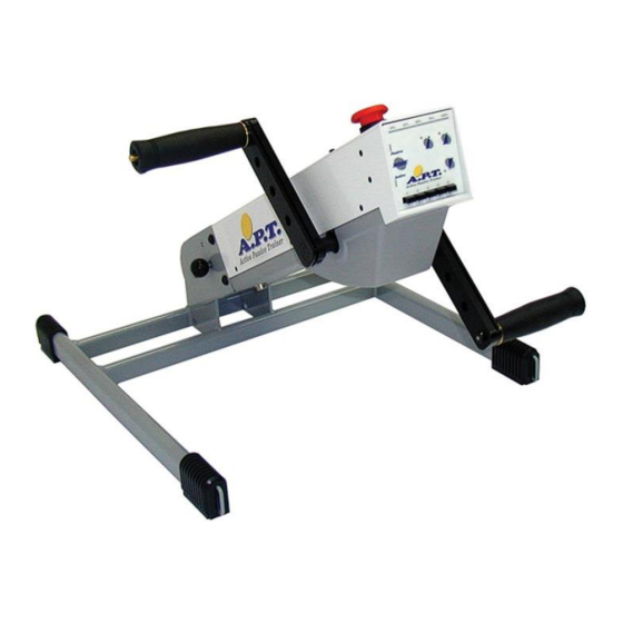
4. SYSTEM COMPONENTS AND DETAILS 4.1 APT-1 unit (Figure 1) APT-1 Hi-Lo (Figure 1A) Operator panel Angle release knob Angle securing knob Crank-arm Power input socket Height release knob (Hi-Lo only) Height securing know (Hi-Lo only) 4.2 Primary components (Figure 2):... - Page 8 2.1. The Type Plate The Type Plate can be found on the underside of the APT-1 body next to the power input socket. Figure 2A This label contains the serial number of the APT-1 The serial number consists of 11 digits and one letter: Example: Serial no.
- Page 9 Button activating Auto-Reverse function in the PASSIVE mode. In the ACTIVE mode this button activates the constant force function. The green indicator is lit when activated. APT-1 – User’s Manual (EU) Rev. 2019-01 en for il...
-
Page 10: Accessories
5. ACCESSORIES The following items are designed for use in combination with the APT-1. CAUTION: The use of accessories other than these can be unsafe. 5.1. Hand grips and Footrests # ACCESSORY USAGE DESCRIPTION FIGURE Straight Used for most of the upper limb exercising. -
Page 11: Section B - User Information
SECTION B – USER INFORMATION 6. PREPARING THE APT-1 HI-LO 6.1. Moving your APT-1 Hi-Lo The APT-1 Hi-Lo can easily be moved by lifting the end of the frame and pushing the unit using its wheels, see Figure 4. 6.2. Positioning the APT-1 Hi-Lo Position the APT-1 Hi-Lo close to an electrical socket outlet. -
Page 12: Installation For Use - Arms Exercise
7. INSTALLATION FOR USE – ARMS EXERCISE Step 1: Position the APT-1 on a level table top close to an electrical socket outlet (Figure 5). For the APT-1 Hi-Lo: loosen the height securing knob (Figure 1A- 7, pull the grey ring of the height release knob (Figure 1A-6) and adjust the unit to the required height. - Page 13 Step 5: Insert handgrip (Figure 9-1) in one of the four mounting holes (Fig- ure 9-2) in each of the APT-1 crank arms. Installation or removal requires only a straight push or pull while simultaneously pressing on the release pin (Figure 9-3) at the end of the handle.
-
Page 14: Installation For Use - Legs Exercise
8. INSTALLATION FOR USE – LEG EXERCISE Step 1: Position the APT-1 on the floor close to an electrical socket outlet (Figure 10). For the APT-1 Hi-Lo: loosen the height securing knob (Figure 1A- 7, pull the grey ring of the height release knob (Figure 1A-6) and adjust the unit to the required height. - Page 15 Power Supply unit. Step 5: Insert Footrest (Figure 13-1) in one of the four mounting holes (Fig- ure 13-2) in each of the APT-1 crank arms. Installation or removal requires only a straight push or pull while simultaneously pressing on the release pin (Figure 13-3) as shown. Secure feet in place with straps fastened diagonally as shown in Figure 10.
-
Page 16: Operation Instructions
9. OPERATION INSTRUCTIONS NOTE: Install APT-1 for arms or legs exercise as described in the previous chAPT-1ers. 9.1. Active mode - ISOKINETIC operation Step 1: Insert the handgrips or footrests in one of the four mounting holes according to the radius and range of motion required. - Page 17 Press the button for backward rotation. NOTE: There will be a short delay before the APT-1 begins to turn in the chosen direction. Step 5: The operation force of the crank arms should rotate the arms or legs of with no effort on the part of the user.
- Page 18 9.4. COMBINED active/passive mode Step 1: Operate the APT-1 in the passive mode and work against the force of the motor by applying resistance to the rotation of the crank arms. Step 2: The resistance force to the rotation is displayed on the on the Bar Indicator as a percentage (%) at each level.
- Page 19 APT-1. 9.7. Emergency Switch In the event of the need to stop the APT-1 quickly, press the red mush- room headed button (Figure 14-1) situated on the top of the trainer body (above the control panel). This will immediately cut the electrical supply to the APT-1.
-
Page 20: Transportation And Storage
10. TRANSPORTATION AND STORAGE The APT-1 can be lifted safely in its folded position by grasping onto the centre of either of the legs of the base unit and carrying like a suitcase. For storage in a confined space, fold the APT-1 unit by pulling the angle release knob (Figure 1-2) and lowering it to the flat position. -
Page 21: Emi - Electromagnetic Interference
11. EMI – ELECTROMAGNETIC INTERFERRENCE CAUTION: It is important that you read this information regarding the pos- sible effects of electromagnetic interference on your APT-1. Electromagnetic Interference (EMI) From Radio Wave Sources The equipment may be susceptible to electromagnetic interference (EMI),... - Page 22 2) Be aware of nearby transmitters, such as radio or TV stations, and try to avoid operating your APT-1 close to them; 3) If an unintended reaction occurs, turn your APT-1 power switch OFF by using the emergency stop switch (see instructions on page 22);...
- Page 23 APT-1 – User’s Manual (EU) Rev. 2019-01 en for il...
- Page 24 APT-1 – User’s Manual (EU) Rev. 2019-01 en for il...
- Page 25 APT-1 – User’s Manual (EU) Rev. 2019-01 en for il...
-
Page 26: Section C - Service Information
The rugged design of the Active Passive Trainer and the use of selected, modern materials ensure minimal requirements for care and maintenance. The APT-1 can be lifted safely in its folded position by grasping on to the centre of either of the legs of the base and carrying like a suitcase. -
Page 27: Disposing And Recycling
The APT-1 device consists of electronic components, cables, plastic parts, steel body and base frame, and aluminium parts. Do not discard any com- ponents to normal refuse facilities. When APT-1 is no longer operational, it is to be dismantled and separated into above material groups and submitted to authorized recycling facilities APT-1 –... -
Page 28: Trouble Shooting
Power Supply connected properly to mains outlet or to the APT-1. APT-1 in standby mode. Press the The APT-1 does not function at button to enter active or passive modes. (Models with Stop-switch) Stop switch in lower - disconnection posi- tion. -
Page 29: Appendix - Exercise Parameter Values
18.5 Power Watts Speed Force 18.5 Power Watts Speed NOTE: Force Levels are indicated for Mounting Hole locations R1, R2, R3 & R4 on crank-arms (Figure 9 / Figure 13). APT-1 – User’s Manual (EU) Rev. 2019-01 en for il... - Page 30 0.13 0.17 0.25 0.50 Force 0.25 Force Force Force NOTE: Force Levels are indicated for Mounting Hole locations R1, R2, R3 & R4 on crank-arms (Figure 9 / Figure 13). APT-1 – User’s Manual (EU) Rev. 2019-01 en for il...
- Page 31 Force 19.7 Speed Force 11.3 11.3 16.9 22.5 Speed NOTE: Force Levels are indicated for Mounting Hole locations R1, R2, R3 & R4 on crank-arms (Figure 9 / Figure 13). APT-1 – User’s Manual (EU) Rev. 2019-01 en for il...
- Page 32 WARRANTY The warranty period for the APT-1 is twelve months and covers faulty ma- terials and workmanship (consumables not covered: plastic coverings and batteries). Worn parts damaged as a result of excessive loading, improper handling, intentional damage or unauthorized maintenance or modification are not covered by the warranty.
Need help?
Do you have a question about the APT-1 and is the answer not in the manual?
Questions and answers