Advertisement
Quick Links
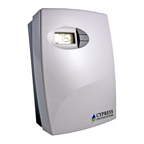
Wireless Pneumatic Thermostat- WPT Series
1
Overview
The Cypress Envirosystems Wireless Pneumatic Thermostat (WPT) retrofits an
existing pneumatic thermostat to provide Direct Digital Control (DDC) like zone control
functionality at a fraction of the time and cost without disturbing occupants.
The WPT enables remote monitoring of zone temperature, branch pressure, remote
control of setpoints, and programmable setback or setup of the pneumatic HVAC
systems. It also enables integration with utility Demand Response programs.
The WPT can be integrated with an existing Building Management System via
BACnet/IP. As a result, the WPT helps a building owner and tenants save energy by
implementing indoor temperature policies, improve comfort, and reduce the
maintenance cost of the legacy pneumatic HVAC systems.
1.1
Components
The WPT Series kit includes the following components:
•
WPT
•
Universal Wall Bracket
•
Mounting screws, #6 x 1" self-tapping (x2)
•
Wall Anchors
•
Tadiran TL-5920 lithium battery
1.2
Prerequisites for Installation
The WPT relies on a wireless network for communication. Before installing the WPT,
the wireless network must be set up. The following tasks must be completed before
proceeding to WPT installation:
•
Installation of WPT Green Box Server and Blue Box Gateway
•
Assignment of a unique node ID for each WPT (to be programmed during
installation)
•
LoRa gateway must be configured with for each WPT. (Please refer to the LoRa
WPT Gateway and Server Installation Manual, Document number 910-00031-
01).
1.3
Tools Required for Installation
•
# 1 Philips-head screwdriver
•
1/16" hex Allen wrench
•
3/16" Drill (for setting Wall Anchor, if required)
2
WPT Installation
The overall WPT installation procedure includes:
•
Mounting the WPT on the wall
•
Configuring the WPT
•
Calibrating the WPT
WPT Quick Start Guide
Document No. 910-00028-01, Rev 03
Page 1 of 21
Advertisement
Troubleshooting

Subscribe to Our Youtube Channel
Related Manuals for Cypress Envirosystems WPT Series


Summary of Contents for Cypress Envirosystems WPT Series
- Page 1 Document No. 910-00028-01, Rev 03 Wireless Pneumatic Thermostat- WPT Series Overview The Cypress Envirosystems Wireless Pneumatic Thermostat (WPT) retrofits an existing pneumatic thermostat to provide Direct Digital Control (DDC) like zone control functionality at a fraction of the time and cost without disturbing occupants.
- Page 2 WPT Quick Start Guide Document No. 910-00028-01, Rev 03 Mounting the WPT 2.1.1 Remove the Existing Thermostat Remove the external cover of the existing thermostat, if any. Locate and remove the mounting screws and carefully remove the unit from the wall along with the attached pneumatic tubes.
- Page 3 WPT Quick Start Guide Document No. 910-00028-01, Rev 03 Do Not Touch Electrical Contacts Figure 1. Handling the WPT Thermostat Lever Handling Precautions • Great care must be exercised while calibrating the WPT. • Handle the thermostat lever as little as possible. •...
- Page 4 WPT Quick Start Guide Document No. 910-00028-01, Rev 03 Calibration Screw Do Not Touch Figure 2. WPT Lever To install the WPT: Remove the plastic cover of the WPT using a 1/16” Allen wrench on the bottom screw. If the Universal Wall-mounting Bracket is attached to WPT, remove it by unscrewing the two captive screws on the bottom of the WPT, as shown in Figure 3.
- Page 5 WPT Quick Start Guide Document No. 910-00028-01, Rev 03 Adjust the Universal Wall Bracket against the old thermostat position, such that any two slots on the wall bracket match the existing two screw holes on the wall, and the large center opening is aligned with the air tube(s). The Universal Wall Bracket is shown in Figure 4.
- Page 6 WPT Quick Start Guide Document No. 910-00028-01, Rev 03 Figure 6. Connecting Main and Branch Tubes to M and B Ports Attach the WPT to the Universal Wall Bracket using the captive screws. Connect the battery and close the top cover. The battery connector is keyed to prevent miswiring.
- Page 7 WPT Quick Start Guide Document No. 910-00028-01, Rev 03 When replacing the battery, press and hold the center button while plugging in the new battery connector. This will reset the battery gauge. When the display appears, release the button. The following tasks must be performed after replacing batteries: •...
- Page 8 WPT Quick Start Guide Document No. 910-00028-01, Rev 03 Configuring the WPT The WPT can be configured using the LCD display and the 3 front buttons. The menu structure is displayed below. Please refer to this diagram while calibrating and configuring the WPT.
- Page 9 WPT Installation Manual Document No. 910-00005-01, Rev 18 Figure 8. WPT Menu Structure Page 9 of 21...
- Page 10 WPT Installation Manual Document No. 910-xxxx-01, Rev 02 2.2.1 Programming Mode Password A password is required to enter the Programming Mode. After pressing all three buttons simultaneously, the following screen will appear: The password is a series of button presses: “OVR”,”OVR”,” ▲”, “▼”, “OVR” contact support@cypressenvirosystems.com for password 2.2.2 Configuring the Frequency Sub-band and Node ID...
- Page 11 WPT Installation Manual Document No. 910-xxxx-01, Rev 02 discovery process, “dy” is displayed on the LCD. During this period, the WPT will turn the motor and calibrate the position of the cam. This process should not be disturbed. Wait for the “dy” to disappear from the LCD before performing any additional operations.
- Page 12 WPT Installation Manual Document No. 910-xxxx-01, Rev 02 Figure 12. Configuring Node ID 4321 After D4 is configured and confirmed, continue to press OVR to exit the Programming Mode. Once Programming Mode is exited, the WPT will rebind to the LoRa network.
- Page 13 WPT Installation Manual Document No. 910-xxxx-01, Rev 02 Calibrating the WPT Remove the front cover of the WPT and make sure that the WPT is acclimatized to the ambient temperature. NOTE: This may take 5 to 10 minutes after attachment to the wall. The bi-metallic spring is very sensitive to body heat.
- Page 14 WPT Installation Manual Document No. 910-xxxx-01, Rev 02 Adjust this screw using a 1/16” Allen wrench to obtain the required control pressure Factory Calibrated Throttling Range Adjuster Tab Figure 14. WPT Calibration Friction Clip Control Lever Figure 15. Friction Clip and Control Lever When the desired control pressure is achieved, press the OVR button to exit and save the value.
-
Page 15: Operation
WPT Installation Manual Document No. 910-xxxx-01, Rev 02 Operation The various indicators and characters that are displayed on the LCD display are shown in the Figure 16. Figure 16. LCD Display The front panel of the LCD display is used to perform the following functions: •... - Page 16 WPT Installation Manual Document No. 910-xxxx-01, Rev 02 During Occupancy Override, the setpoint will revert to the last “Occupied” value as commanded by the server. During the override duration, the LCD displays the OVR indicator. Measuring the Branch Line Pressure To measure the branch line pressure: •...
- Page 17 WPT Installation Manual Document No. 910-xxxx-01, Rev 02 LoRa Over-The-Air Activation (OTAA) The WPT uses LoRa OTAA to create a connection link to the network. NOTE: Force discovery before a WPT is bound to the LoRa network will cause an error.
-
Page 18: Troubleshooting
WPT Installation Manual Document No. 910-xxxx-01, Rev 02 Troubleshooting The WPT is designed with diagnostic functions to detect and diagnose faults. Code Reason Solution Discovery Status: This code indicates that the • This indication disappears automatically WPT is performing a discovery after a few seconds. -
Page 19: Additional Troubleshooting
WPT Installation Manual Document No. 910-xxxx-01, Rev 02 Additional Troubleshooting Symptoms Possible Solution For 2 pipe WPTs: 1. First check that the rubber cap is firmly bottomed into port stub as shown in Figure 17 below. 2. Remove the WPT from the Universal Wall Bracket. 3. - Page 20 WPT Installation Manual Document No. 910-xxxx-01, Rev 02 Rubber Port Cap below Hose on Port Stub Figure 17. 2 Pipe Thermostat Port Cap Repair Except for the batteries, the WPT does not have any field replaceable or repairable parts. Contact the original distributor of the unit for repair or warranty service. NOTE: Care should be taken to keep the unit dust-free during installation.
-
Page 21: Technical Specification
Storage Conditions 95%RH Max, Noncondensing Length: 5.6 in (141 mm ) Dimensions Width: 4.1 in (104 mm ) Depth: 2.1 in (53 mm ) Cypress Envirosystems 5883 Rue Ferrari San Jose, CA 95138, USA info@cypressenvirosystems.com support@cypressenvirosystems.com Phone: +1 (408) 943-2800...
Need help?
Do you have a question about the WPT Series and is the answer not in the manual?
Questions and answers