Table of Contents
Advertisement
Advertisement
Table of Contents
Troubleshooting

Related Manuals for Sinexcel PDS1-750K-H


Summary of Contents for Sinexcel PDS1-750K-H
- Page 1 PDS1-750K-H DC converter Manual...
- Page 2 Data Version V1.0 Filed on 2022-06 Shenzhen Sinexcel Electric Co., Ltd. All rights reserved. In case of any content change, it shall be without prior notice. Shenzhen Sinexcel Electric Co., Ltd. Website: http://sinexcel.us/ or www.sinexcel.com Add: Building 6, Area 2, Baiwangxin High-tech Industrial Park, No. 1002, Songbai Road, Nanshan District,...
-
Page 3: Table Of Contents
Table of Contents 1 OVERVIEW ................................. 5 ............................... 5 1.1 A PPLICABLE MODELS ................................5 1.2 T ARGET ROUP ........................ 6 1.3 N OMENCLATURE ERMS AND ABBREVIATIONS 2 SAFETY PRECAUTIONS ............................7 ..................................7 2.1 S YMBOLS ..........................7 2.2 I MPORTANT AFETY INSTRUCTIONS ............................. - Page 4 6.3.6 Wiring Precautions ..............................28 6.3.7 Overview of the wiring area ..........................28 6.3.8 Power line wiring ..............................30 6.3.9 Ground connection ..............................31 6.3.10 Installation Checklist ............................32 7 PRODUCT RUNS ..............................33 .............................. 33 7.1 C HECK BEFORE RUNNING 7.1.1 Check cable connections ............................
- Page 5 ....................61 10.2 LED INDICATOR SHOWS TROUBLESHOOTING METHOD ..........................62 10.3 C OMMON FAULTS AND SOLUTIONS ................................64 10.4 O THER FAULTS 11 MAINTAIN ................................65 ..............................65 11.1 S AFETY RECAUTIONS ..........................65 11.2 M AINTENANCE WORK AND CYCLES ..........................
-
Page 6: Overview
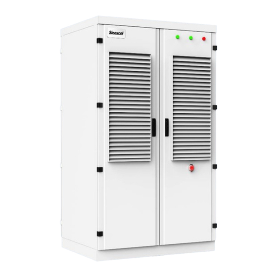
The illustrations in this document have been reduced to be necessary and may differ from the real product. The PDS1-750K-H energy storage converter is a series of converters; the rated converter capacity is 750kW, and the number of modules fully loaded is 8 modules. -
Page 7: Nomenclature Terms And Abbreviations
1.3 Nomenclature Terms and abbreviations 名称 定义 Direct current Bus side BESS Battery energy storage system Energy storage system. Energy management system. Battery management system. Power conversion system. Single line diagram State of health (of battery), expressed in percentage. Silicon controlled rectifier Depth of discharge, the rest battery capacity, expressed in percentage. -
Page 8: Safety Precautions
NOTE is used to address information that is not related to personal injury, equipment damage, and environmental degradation. 2.2 Important Safety instructions This user’s manual is about installation and operation of Sinexcel PDS1 series 750kW Bi-directional DC converter. Before installation, please read this user’s manual carefully. -
Page 9: Additional Information
The components behind the protective cover plate and dam board which are opened by tools cannot be maintained by users. Please read this user’s manual before operation. 2.3 Additional Information Links to additional information can be found at http://sinexcel.us/ or www.sinexcel.com. -
Page 10: Product Introduction
3 Product Introduction 3.1 System Introduction Bidirectional DC converter is usually a conversion device between photovoltaic and battery, photovoltaic power generation can charge the battery. It can also be a conversion device between the battery and the DC bus, the battery can be discharged to the DC bus, and the DC bus can charge the battery. -
Page 11: System Schematic
Battery Battery Internal bus buck-boost bridge Internal bus Fig 3.3 Schematic diagram of bidirectional DC converter circuit system PDS1-750K-H consists of 8 DC modules, the DC side can be used as 1/2/4 branch, and the BUS side is 1 branch. -
Page 12: Module Introduction
3.4 Module introduction Fig 3.4 Front View of DC Module Position Description Description Rear power plug-in terminals white - high pressure Communication, Multi-function indicator port dial code, indicator light Module fixing ears hanging ears not load bearing handle Fig 3.5 Schematic diagram of the multi-function indicating terminals of the DC module silk screen describe directions... -
Page 13: Dimensions And Weight
3.5 Dimensions and Weight The dimensions of the PDS1-750K-H DC converter are shown in Figure 3.7. The net weight of the product is about 845kg, and the specific weight is based on the actual standard. Fig 3.7 Dimensions of PDS1-750K-H... -
Page 14: Heat Dissipation And Fire Protection
3.6 Heat dissipation and fire protection The PDS1-750K-H DC converter is an IP54 outdoor unit. It adopts the structure design of front air and rear air outlet. The outdoor air enters through the air intake window at the front of the DC converter, and the hot air is discharged through the exhaust port on the back of the converter. -
Page 15: Specifications
- handle up Isolation switch (turn counterclockwise) - handle horizontally Circuit breaker position (toggle down) - handle down 4 Specifications Technical Data Sheet model PDS1-750K-H rated power 750kW Max power 825kW DC side voltage range 500~1500V Number of DC side... -
Page 16: Storing、Lifting And Transporting
5 Storing、lifting and transporting 5.1 Transport and storage In order to ensure that the energy storage converter is in a better protective state during transportation, please choose to transport with packaging as much as possible, and transport according to the indications of various signs on the packaging. -
Page 17: Transfer
The energy storage converter is a whole device, and it must not be disassembled during transportation or storage. Equipment failures caused by modifications not authorized by Sinexcel are not covered by the warranty. When the equipment is transported and stored, it is strictly forbidden to stack, and no other items are allowed to be stacked on the top of the equipment. - Page 18 In the process of using a forklift to fork, lower and move the energy storage converter, it is necessary to ensure that it is slow and stable, and the energy storage converter must be placed on a firm and level ground. In the entire process of using a forklift to operate, it is necessary to strictly abide by the forklift safety operation specifications.
-
Page 19: Out Of The Box Inspection
No matter which way you choose to move the energy storage inverter, you must ensure: ⚫ Must always pay attention to the position of the center of gravity. ⚫ Must be considered the volume and weight at all times. ⚫ Must be ensured the safety of operators at all times. - Page 20 Check the DC converter for deformation, peeling paint and loose parts. The packing list of the PDS1-750K-H DC converter is shown in Table 5-2. Table 5-2 Packing list serial number name quantity PDS1-750K-H-DC converter 1 set (including cabinet door key and related accessories)
-
Page 21: Device Installation
6.1 installation requirements 6.1.1 Basic requirements The protection level of the PDS1-750K-H DC converter is IP54, which can be installed outdoors, but cannot be placed in a high-humidity environment for a long time. Due to the noise generated during operation, the energy storage inverter should be installed in a location far away from residential areas, and the installation location should not contain corrosive and flammable gases. -
Page 22: Foundation Support Requirements
6.1.3 Foundation Support Requirements The DC converter needs to be installed on the concrete foundation or the structure supported by the steel channel with the surface of the flame retardant material. It must be ensured that the foundation is flat, solid, safe and reliable, and has sufficient bearing capacity. -
Page 23: Ventilation Requirements
The fan outlet of the PDS1-750K-H DC converter is located at the bottom of the device. The location where the DC converter is installed should ensure that there is enough air duct space before and after the converter according to the requirements of 3-4, otherwise it will seriously affect the operation and operation of the DC converter. -
Page 24: On-Site Installation
The DC converter should not be installed in places with poor ventilation and low airflow. There should be sufficient fresh air supply at the air inlet. The air quality must be guaranteed. If the content of suspended matter such as sand and dust in the air is too large, the air purity can be improved by installing filters at the air supply grille. -
Page 25: Fixed Dc Converter
6.2.2 Fixed DC Converter If the DC converter is finally fixed on the channel steel, before the equipment is finally fixed, it is necessary to ensure that the laying of the cable trench and the opening of the channel steel meet the requirements for the bottom size and fixing holes in Section 6.1.3 of the DC converter. -
Page 26: Electrical Connections
6.3 Electrical connections 6.3.1 General Safety Danger of electric shock! Before installation, make sure that the installation cables and equipment are not powered. The internal capacitor of the DC converter is a dangerous energy storage device. Do not place inflammable and explosive materials near the DC converter. -
Page 27: Wiring Parts
⚫ Wire strippers ⚫ Terminal crimping machine ⚫ Hot air gun (or hot air blower) ⚫ Multimeter 6.3.3 Wiring Parts The fixing screws and other parts used for the wiring of the power cable of the DC converter have been packaged in a unified packaging bag when the device is delivered. -
Page 28: Cable Requirements
from the bottom of the machine. In order to prevent foreign objects from entering and leaving the machine during transportation, the delivered equipment has a wire inlet baffle at the bottom, and the wire inlet baffle needs to be removed before wiring. 6.3.5 Cable Requirements The cable selection requirements are as follows: ⚫... -
Page 29: Wiring Precautions
6.3.6 Wiring Precautions Insulation and integrity checks of all connecting cables are required prior to all electrical wiring. It is strictly forbidden to use cables with poor insulation, partially exposed or otherwise damaged cables. Before wiring, make sure the polarity of the cables on either side is correct. During the wiring process, do not pull the cable hard to avoid damaging its insulation performance. - Page 30 Fig 6-5 Schematic diagram of the battery side terminals (front of the device) Fig 6-6 Schematic diagram of the wiring terminal on the bus side (the back of the device) Fig 6-7 Communication port wiring diagram (control box panel)
-
Page 31: Power Line Wiring
6.3.8 Power line wiring Before wiring either side, the following checks should be made: ⚫ Measure the open-circuit voltage of the battery/bus group to ensure that the open-circuit voltage is within the normal DC voltage range of the DC converter. ⚫... -
Page 32: Ground Connection
6.3.9 Ground connection The grounding cable must be well grounded, otherwise: ⚫ In the event of a malfunction, there may be a fatal click hazard to the operator. ⚫ May cause equipment damage when struck by lightning. ⚫ May cause the device to fail to operate normally. Before leaving the factory, the shell of the DC converter and the components that need to be grounded in the cabinet have been reliably connected to the grounding copper bar at the bottom of the machine. -
Page 33: Installation Checklist
6.3.10 Installation Checklist After all the DC converters are installed, at least two staff members are required to conduct a comprehensive inspection of the installation according to the items listed in Table 3-5. Records should be made during the inspection process. -
Page 34: Product Runs
7 Product runs 7.1 Check before running Before the first operation or after completing maintenance and overhaul, the installation of the equipment should be thoroughly checked again. All operations during operation must be performed by professional electrical personnel, and any individual shall not operate without authorization. -
Page 35: Check Battery/Bus Side Voltage
The voltage on either side shall not exceed the maximum DC voltage allowed by the energy storage inverter, Excessive DC voltage can damage equipment or even cause safety accidents. 7.2.3 Check battery/bus side voltage ⚫ Accurately measure the voltage on either side, and the measured value should not exceed the allowable DC voltage range on the battery/bus side of the DC converter. -
Page 36: Stop
7.2.2 Stop Stop is usually divided into two situations: shutdown during normal maintenance or overhaul and shutdown during emergency. To stop during normal maintenance or overhaul, follow the steps below: ① Control the shutdown of the DC converter through the "stop" operation command on the LCD touch screen。 ②... -
Page 37: Operating Mode
7.3 Operating mode 7.3.1 Main function PDS1-750K-H DC converter has the following functions: ⚫ Local manual The DC converter is operated by local monitoring or webpage monitoring for on-off, charging and discharging, and is scheduled locally. ⚫ Local automatic The DC converter is subject to local monitoring or the automatic operation DC and operation strategy set by the webpage monitoring to perform on-off, charging and discharging operation, and is scheduled by the local strategy. -
Page 38: Introduction To Work Status
7.3.2 Introduction to work status The PDS1-750K-H DC converter has several states such as "initial stop", "stop", "run", "fault" and "emergency shutdown". ⚫ Initial stop In this state, the system performs a self-check, and when the self-check is passed, the converter transfers from the initial shutdown mode to the shutdown mode. -
Page 39: Protective Function
7.4 Protective function serial protected serial Protected number name number name Overvoltage and Emergency stop protection undervoltage protection Overcurrent and overload Repeated start and stop protection protection Module current abnormal reverse polarity protection protection Power input over and under Short circuit protection voltage protection Communication fault Power output over-voltage... -
Page 40: Lcd Touch Screen Operation Guide
8 LCD touch screen operation guide 8.1 LCD touch screen function and menu introduction The LCD touch screen is located on the front of the door of the DC converter. Users can issue various operation commands through the LCD touch screen to easily browse various operation-related parameters and working states, and obtain the current working conditions and alarm information of the DC converter in time. -
Page 41: Main
The LCD touch screen contains a large number of parameters related to the operation of the DC converter. All settings such as parameter modification must be completed by designated professionals. For parameters whose meaning is unclear, do not modify them without authorization. 8.2 Main page introduction 8.2.1 Start page When the DC converter is powered on, the LCD touch screen will automatically start up, and the startup page will be... -
Page 42: Operation Information Menu Introductio
8.3 Operation information menu introductio Click the running information menu on the main page to enter the secondary menu display interface of running information. When the secondary menu interface has multiple pages, only the home page is displayed in this section, and the contents of other pages are fully listed in the description section. -
Page 43: Introducing The Event Log Menu
BMS Information Secondary Submenu Display battery-related voltage, SOC, current, and status information. 8.4 Introducing the Event Log Menu Click the event record menu on the main page to enter the secondary menu display interface of the event record. When the secondary menu interface has multiple pages, only the home page is displayed in this section, and the contents of other pages are fully listed in the description section. - Page 44 Historical alarm secondary submenu show that has appeared, However, various alarm information has been cleared in the current situation. Status Record Secondary Submenu Displays the state change log of the DC converter. Operation record secondary submenu Displays the command record issued to the DC converter.
-
Page 45: Control Scheduling Menu Introduction
Curve record secondary submenu You can choose to display DC voltage, DC current, DC power and temperature curves. Record Export Secondary Submenu Provide download history alarms, download operation records, download fault records and download status records, historical data or all records to mobile storage. 8.5 Control scheduling menu introduction Click the control scheduling menu on the main page, and the operation password input box will pop up first. - Page 46 After the user enters the correct operation password, it will enter the secondary submenu of control scheduling Control Command Secondary Submenu It can control the startup, shutdown and fault reset functions of the DC converter (note that the fault reset function should not be used arbitrarily).
-
Page 47: System Settings Menu Introduction
8.6 System settings menu introduction Click the system setting menu on the main page, and the operation password input box will pop up first, please refer to 5.5 for related login operations. After the user enters the correct operation password, the user will enter the secondary submenu of system settings. Model Settings Secondary Submenu Users can check the model, working mode, Soft start mode, etc. -
Page 48: Operation Mode Menu Introduction
Monitoring settings secondary submenu Users can set the IP, subnet mask, network management, Server IP, communication baud rate, language, Backlight time and factory reset, etc. DC Settings Secondary Submenu The user can set the DC upper/lower limit voltage of the converter, Discharge termination voltage, maximum charging current,... -
Page 49: Operation Strategy Menu Introduction
Operation Mode Secondary Submenu The user can set the operation mode of the DC converter: local control, local automatic and remote control. 8.8 Operation strategy menu introduction Run Strategy Secondary Submenu The user can set the charging and discharging status and the corresponding charging and discharging power at different times of the day. -
Page 50: About This Machine's Menu Introduction
8.9 About this machine's menu introduction On the main page, click the About This Machine menu to enter the About This Machine menu interface. About the local submenu interface Display serial number, MAC, CPLD version, monitor version。... -
Page 51: Introduction To Web Monitoring
9 Introduction to Web Monitoring 9.1 WIFI webpage background function and menu introduction In addition to the human-computer interaction mode of the LCD touch screen, the DC converter also has a WIFI web page background interaction mode, which is convenient for users to view data and perform related operations. Users can use mobile phones, tablets, laptops and other devices with WIFI and web browser functions, through manual link (default WIFI name: DC converter serial number, default password: 080808) or scan the code of the DC converter body Connect the QR code on the DC converter to the WIFI hotspot of the DC converter, then open the... -
Page 52: Lan Port Lan Connection
9.3 LAN port LAN connection: Take the use of control box LAN2 as an example: a. The PC is directly connected to the LAN port of the control box, and the PC port is configured with IPv4 manual settings, so that the PC and the control box are in the same network segment: b. -
Page 53: Operation Information Menu Introduction
9.4 Operation information menu introduction After the user enters the correct username and password to enter the background of the web page, click on the running information to enter the secondary menu display interface of the running information. When the secondary menu interface has multiple pages, only the home page is displayed in this section, and the contents of other pages are fully listed in the description section. -
Page 54: Introducing The Event Log Menu
BMS Information Secondary Submenu Display battery related voltage, current, SOC and charge and discharge status information, etc. 9.5 Introducing the Event Log Menu Click the event record menu to enter the event record secondary menu display interface. When the secondary menu interface has multiple pages, only the home page is displayed in this section, and the contents of other pages are fully listed in the description section. - Page 55 Historical alarm secondary submenu show that has appeared, However, various alarm information has been cleared in the current situation. Status Record Secondary Submenu Displays the state change log of the DC converter.
- Page 56 Operation record secondary submenu Displays the command record issued to the DC converter. Record Export Secondary Submenu Provides download of all recorded files to the local browser download directory.
-
Page 57: Control Scheduling Menu Introduction
9.6 Control scheduling menu introduction Click the control scheduling menu to enter the secondary submenu of control scheduling, including control command settings and scheduling command settings. Control Command Secondary Submenu It can control the startup, shutdown, and fault reset function (Note that the fault reset function should not be used arbitrarily). -
Page 58: Introduction To The Settings Menu
9.6.1 Introduction to the settings menu Clicking the system setting menu will enter the secondary submenu of system setting, including system setting, monitoring setting and DC setting. System Settings Secondary Submenu This interface is a custom interface, If necessary, please contact our engineers for relevant sub-settings Monitoring settings secondary submenu Users can set the IP, subnet mask, network... -
Page 59: Operation Strategy Menu Introduction
9.6.2 Operation strategy menu introduction Click the Run Mode menu to enter the second level submenu of Run Mode, including Run Mode and Strategy. Operation Mode Secondary Submenu The user can set the operation mode of the DC converter: local control, local automatic and remote control. -
Page 60: Login Menu Introduction
9.7 Login menu introduction Click the login menu to enter the login menu interface. User interface after successful login Users can log in, log out and modify passwords with more advanced permissions on this interface. 9.8 About this machine's menu introduction Click the About This Machine menu to enter the About This Machine menu interface. -
Page 61: Troubleshooting
10 Troubleshooting Only qualified technicians should perform the operations described in this chapter. "Meeting the requirements" means that the operator has previously participated in professional training on various operations of equipment troubleshooting. Only perform troubleshooting as described in this manual. When operating, follow all safe operating practices. -
Page 62: Led Indicator Shows Troubleshooting Method
10.2 LED indicator shows troubleshooting method Please refer to the following table for device status description: Table 10-1 DC-DC converter cabinet status State Condition Operating status Power-off Disconnect BUS, DC power supply The lights on the device are all off Power-on Close BUS, DC power supply The power light on the device is on... -
Page 63: Common Faults And Solutions
Indicates that the DC converter is not running 1) Check whether the DC wiring is correct, use a multimeter to measure the DC input voltage, and ensure that the voltage value exceeds the starting voltage of the DC converter. RUN indicator does not light up 2) Ensure that the DC power supply and various parameters meet the operating requirements of the DC converter. - Page 64 voltage, PV wake-up voltage, DC output voltage Check whether the BUS side voltage parameter settings conflict: bus side overvoltage protection setting, bus side undervoltage protection setting, bus side voltage operation upper limit, bus side voltage operation lower limit Monitoring The parameters under monitoring are beyond the 1.
-
Page 65: Other Faults
failure displayed the module panel No. 2. Modules with duplicate IDs are offline When a single-channel BMS dry node is connected, BMS failure Check the connection problem of the BMS dry node. the BMS dry contact is open Alarm classification: Fault - Hardware shutdown failure. -
Page 66: Maintain
11 Maintain Due to the influence of ambient temperature, humidity, dust and vibration, the components inside the DC converter will age and wear out, which will lead to potential failures inside the DC converter. Therefore, it is necessary to carry out daily and regular maintenance on the DC converter to ensure its normal operation and service life. - Page 67 ⚫ Observe whether the DC converter is damaged or deformed ⚫ Listen to whether there is any abnormal sound in the operation of the DC converter ⚫ When the system is running, check whether the variables are abnormal ⚫ Check whether the main components are normal System operating status and ⚫...
-
Page 68: Check And Replace Dust Cotton
t is necessary to regularly check whether the fan of the cabinet module is running normally, and observe whether there is a friction noise during operation. If there is, it may be caused by the entry of dust, and the dust needs to be removed after the DC converter is stopped. -
Page 69: Replace Electrical And Electronic Components
11.4 Replace electrical and electronic components When replacing the electronic and electrical components in the DC converter, be sure to replace the components of the same manufacturer and the same model. The model of the component can generally be obtained through the identification of the product itself. -
Page 70: Appendix
12 Appendix 12.1 Customer dry contact and communication port description COM1 COM2 Para1 Para2 Module-COM POWER COM3 COM6 FAULT COM4 COM7 LAN1 LAN2 Monitor COM5 COM8 WIFI Terminal schematic: 1. EPO is the emergency stop button; Indicates pin 1 of the terminal COM3-1 EXT_OUT1 COM4-1 Dry_OUT1_DRV COM5-1 Dry_IN1_DRV... -
Page 71: Contact
• Battery Type and number • Communication type • Firmware version • Error number and error message Shenzhen Sinexcel Electric Co., Ltd. Website: http://sinexcel.us/ www.sinexcel.com Add: Building 6, Area 2, Baiwangxin High-tech Industrial Park, No. 1002, Songbai Road, Nanshan District,...
Need help?
Do you have a question about the PDS1-750K-H and is the answer not in the manual?
Questions and answers