Table of Contents
Advertisement
Quick Links
Advertisement
Table of Contents
Troubleshooting

Related Manuals for Sinexcel PDC-400K


Summary of Contents for Sinexcel PDC-400K
- Page 1 User Manual DC-DC Converter...
- Page 2 Sinexcel DC-DC Converter User Manual Version: V1.2 Shenzhen Sinexcel Electric Co., Ltd. All rights reserved. In case of any content change, it shall be without prior notice. Shenzhen Sinexcel Electric Co., Ltd. Website: http://sinexcel.us/ www.sinexcel.com Add: Building 6, Area 2, Baiwangxin High-tech Industrial Park, No. 1002, Songbai Road, Nanshan District,...
-
Page 3: Table Of Contents
Table of Contents 1 Information on this Document ............................4 1.1 Validity ................................... 4 1.2 Target Group ................................4 1.3 Nomenclature Terms and Abbreviations ........................5 2 Safety Precautions ................................6 2.1 Symbols..................................6 2.2 Important Safety instructions ............................ 6 2.3 Additional Information .............................. - Page 4 8.3.3 Select Control Mode............................30 8.3.4 General Settings ..............................30 8.3.5 Communication setting ............................. 30 8.4 Manual Startup Procedure ............................31 8.5 Automatic Startup Procedure ........................... 31 8.6 Remote Startup Procedure ............................31 8.7 Shutdown Procedure ..............................31 8.8 System Power Off ..............................31 8.9 Emergency shutdown ...............................
-
Page 5: Information On This Document
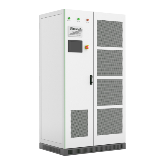
DC-DC Converter Fig.1-1 Product model definition For example: PDC-400K: 400kW DC-DC Converter. PDC-150K: 150kW DC-DC Converter. Check the type label for the production version of PCS. The illustrations in this document have been reduced to be necessary and may differ from the real product. -
Page 6: Nomenclature Terms And Abbreviations
1.3 Nomenclature Terms and Abbreviations Terms Definition Static Transfer Switch Alternative current. Direct current. BESS Battery energy storage system Energy storage system. Energy management system. Battery management system. Power conversion system. Single line diagram State of health (of battery), expressed in percentage. Silicon controlled rectifier Depth of discharge, the rest battery capacity, expressed in percentage. -
Page 7: Safety Precautions
NOTE is used to address information that is not related to pers onal injury, equipment damage, and environmental degradation. 2.2 Important Safety instructions This user’s manual is about installation and operation of Sinexcel PWS1 series 500kW Bi-directional Energy Storage converter (PCS). Before installation, please read this user’s manual carefully. -
Page 8: Additional Information
The components behind the protective cover plate and dam board which are opened by tools cannot be maintained by users. Please read this user’s manual before operation. 2.3 Additional Information Links to additional information can be found at http://sinexcel.us/ or www.sinexcel.com. -
Page 9: Product Introduction
The 400Kw DC-DC DC converter converts the DC power of the PV module array into DC power that can charge the battery. PDC-400K series DC-DC converter use the single-stage topology, wide PV input range: 250-650V; voltage range for output to battery: 600-900V, the more detaled parameter can be seen in chapter below. - Page 10 with SPD protectors, DC circuit breakers and auxiliary power distribution units. Figure below is a topological diagram of the composition. DC Breaker 1 PCS-DC Module 1 PCS-DC Module, n=1~8 PV 1 DC Breaker Battery DC SPD DC Breaker n PCS-DC Module n PV n DC Breaker, n=1~8 DC SPD...
-
Page 11: Dc-Dc Converter Composition
3.4 DC-DC Converter Composition Figure3-3: Visible Components of the DC-DC 8 string MPPT single string MPPT Position Designation Description Indicator lights Touch Screen EPO (Emergency Power Off) PCS-DC (1~8 module(s)) 50KW for1 set Battery DC Branch Switch 1 to 8 set DC Branch Switch U2 Main control board Main DC Switch Wiring terminal... -
Page 12: Operating Compositions
3.5 Operating Compositions 3.5.1 Switches Introduction 3.5.1.1 DC Switch The DC disconnection unit disconnects the PCS from the Battery module arrays. The NA series PCS breaker is comply to the UL certification. ▽ Figure 3-5: Indicators on the DC load-break switch Position Designation Explanation... -
Page 13: Touch Screen
Switch position In (On) The DC disconnection unit is closed. Central switch position The DC disconnection ▽ Switch position off The DC disconnection Unbuckle recovery: take the switch to the off first before taking the switch to the on. 3.5.1.3 AUX power supply Switch AUX power supply can be the redundancy power supply through the AC Switch inside the PCS cabinet. -
Page 14: Leds Of The System
Figure 3-7 UI Design of the touch display Position Designation Explanation Menu Menu can be different before/after log-in and other setting. System Topology Version and time 3.5.2.2 Symbols Explanation Symbol Designation DC side DC Module PV Solar Switch on DC or AC side open Switch on DC or AC side closed 3.5.3 LEDs of the System The appearance of the PCS is shown in below. -
Page 15: Labels
Figure 3-8 LEDs on the front panel LED designation Description Explanation Fault indicator light Normal indicator light Power indicator light Touch screen Emergency shutdown button Figure 3-9 Front view for PCS-DC module LED designation Description Explanation Normal indicator light Green Fault indicator light DIP switch Address... - Page 16 Label Explanation Label-Dot label-A phase Label-Dot label-B phase Label-Dot label-C phase Label-Dot label-Negative electrode Label-Dot label-Negative electrode Label-Dot label-Negative electrode Label-Dot label-Neutral line Label-Dot label-Grounding Label-Warning label-Danger High Voltage Label-Warning label-Danger large leak current...
-
Page 17: Technical Data
4 Technical Data Technical parameters table (400KW) Specification PDC-400K LV PV input mode (Default) HV DC bus voltage LV voltage+40V ~ 850V HV DC bus current 0~100A× 8 LV PV input voltage 250~840V LV PV input current 0~130A× 8 Power rating 50kW×... - Page 18 Application environment restrictions: When the DC-DC Converter is working in stand-alone mode, there are some restriction to the application environment. •Several DC-DC Module independent working is the customized function.When require the multi-string input and multi-string output, please contact manufacture to do the customization.
-
Page 19: Storing, Lifting And Transporting
5 Storing, lifting and transporting 5.1 Safety during Transport If the lifted or suspended load falls over, falls or sways, there is a risk of crushing Vibration or careless or hasty lifting and transport can cause the product to tip over or fall. This can result in death or serious injury. -
Page 20: Installation
6 Installation 6.1 Safety during Installation Risk of electric shock caused by live voltage There is a high voltage in the live components of the product. Touching field components can result in death or seriousness electric shock damage. Wear appropriate personal protective equipment for all work on the product. Do not touch any live components. -
Page 21: Mechanical Installation
6.2 Mechanical Installation 6.2.1 Mounting preparation Drilling Mounting Holes is required in the Foundation. The overall dimension of the DC-DC Converter is shown in figure below. Fig. 6-1 Overall dimensions of the DC-DC Converter cabinet, width: 800mm, height: 2160mm (without lifting rings); depth: 1100mm. Green threshold height 60mm,If you don't have enough height to enter the room, you can take it off. -
Page 22: Preparation For Mounting On A Base
Fig. 6-2 the DC-DC Converter rack wiring hole in bottom view There are two hole in each corner, only one hole need to mount bolts, the other hole is used as a spare. 6.2.2 Preparation for Mounting on a Base After the rack is removed to the installation position of BESS (battery energy storage system) with a forklift or a tool. -
Page 23: Output Requirement
6.3.2 Output requirement The DC-DC cabinet output is DC that charges the battery. Maximum current can be 390A. 6.3.3 Wiring mode The wiring mode of the The DC-DC cabinet is down inlet and down outlet, the incoming and outlet wiring holes located in bottom of the PCS cabinet. The cables put into the cable trough via the wire holes at the base. -
Page 24: System Grounding
Table 6-3 description for wiring components of DC-DC cabinet 6.3.4 System grounding The modules in the DC-DC cabinet realize grounding connection with the rack through hangers. As for rack grounding, the rack bottom is installed with grounded cooper bars. During wiring, refer to the following table for cable diameter. -
Page 25: Dc Port Wiring
Rack and modules need to be grounded reliably! The grounding resistance should be less than 4Ω. 6.3.5 DC port wiring The DC port wiring should be done before power on, the detailed DC port wiring could be seen in installation manual. - Page 26 Fig. 6-8 Wring and communication interface position Table 6-6 Communication interface description Interface Description Explanation position Terminal strip ports RS485 , CAN, (AS BELLOW) Touch Screen Ethernet port Shown as 6.10 Communication interface...
-
Page 27: Communication Interface Connection
Fig. 6-9 Definition of terminal strip ports Fig. 6.10 Definition of touch screen communication ports The LAN (Ethernet) port is used for communication. The USB port is used for system update or the logs export. The other communication ports in the back of touch screen has been wired to the wiring terminal strip ports. -
Page 28: Connecting The Ems Over Rs485 Or Ethernet
When directly connecting to the BMS, the communication port is default as CAN as shown below. If the BMS use Ethernet communication port, a Ethernet-CAN protocol converter is needed . That Ethernet-CAN protocol converter should be bought by the user and its beyound Sinexcel’s scope of supply. -
Page 29: Function Description
7 Function Description 7.1 Operating Status 7.1.1 Overview of the Operating Status Refer to the following table for status of DC-DC converter. Table 7-1 Status of DC-DC converter Status Condition Running mode Powere PV,Battery switch disconnected The lights on the equipment are all out. d off PV,Battery switch connected The power on the equipment is on. -
Page 30: Setting Procedure Before Startup
close the switch in sequence. Power on every time: 1): Check whether the EPO button in reset state. 2): Close the switch in sequence. Firstly close the PV switch, then close the BATTERY switch. 8.3 Setting Procedure before startup 8.3.1 Touch screen power on After auxiliary power of the DC-DC converter is connected, THE HMI is on. -
Page 31: Select Control Mode
8.3.3 Select Control Mode Main menu structure can be different in different “Ctrl Mode”. Configuring the control mode 1. Select “User”, Log into the control interface on touch screen with password. 2. Select “Ctrl Mode” > “Manual Operate” Then the “Settings” is visible. 8.3.4 General Settings Fig. -
Page 32: Manual Startup Procedure
etc. can be set as needed; 4.If there are multiple devices on the scene, different modbus device addresses need to be set up in order to distinguish; 8.4 Manual Startup Procedure Check before startup: 1. Select “User”, Log into the control interface on touch screen with password. 2. -
Page 33: Troubleshooting
To prevent personal injury, please use a multi-meter to measure the voltage at input terminal if case maintenance or opening is conducted. After ensuring that there is no mains supply, relevant operation can be conducted! After about 15 minutes, the upper cover plate can be opened after DC BUS bar capacitance fully discharges (refer to warning label on module case surface). -
Page 34: Detailed Troubleshooting
Manual: After the cause of the alarm disappears, you need to manually send an alarm clear command. Power Off: After the causes of the alarm disappear, you need to power off and restart. Alarm Classification + Clearance Method (abbreviate to A.C. + C.M.): Fault + Auto Fault + Manual Fault + Power Off... -
Page 35: Maintenance
10 Maintenance 10.1 Safety during Maintenance There is a high voltage in the live components of the product. Touching field components can result in death or seriousness electric shock damage. Wear appropriate personal protective equipment for all work on the product. Do not touch any live components. -
Page 36: Electrical And Fixed Connection Inspection
If the DC power distribution parts is affected by adverse environmental conditions, it is recommended to shorten maintenance interval. Sinexcel recommends an optical inspection in regular periods to determine maintenance requirements Consumables and maintenance materials Only those consumables and maintenance materials are usually not included in standard equipment list. -
Page 37: Contact
• Battery Type and number • Communication type • Firmware version • Error number and error message Shenzhen Sinexcel Electric Co., Ltd. Website: http://sinexcel.us/ www.sinexcel.com Add: Building 6, Area 2, Baiwangxin High-tech Industrial Park, No. 1002, Songbai Road, Nanshan District,... -
Page 38: Appendix 1 Settings On Hmi (Touch Screen)
Appendix 1 Settings on HMI (Touch Screen) 12.1 Touch Screen Startup Operation control can be conducted via HMI (human-computer interface). This section introduces the HMI display content and settable parameters. The ”Home”, ”Info”, ”Logs”, ”User” can always be seen before log-in with a password. The detailed menu structure can be seen as below. -
Page 39: Log Into The Control Interface
12.1.2 Log into the control Interface 1. Select “User”, Log into the control interface on touch screen with password. 2. User can get the password from the authorized person/ party / agency/ etc. The login password 123456789 can obtain administrator authority. Hierarchical password function, different password have different administration authority.
Need help?
Do you have a question about the PDC-400K and is the answer not in the manual?
Questions and answers