Advertisement
Quick Links
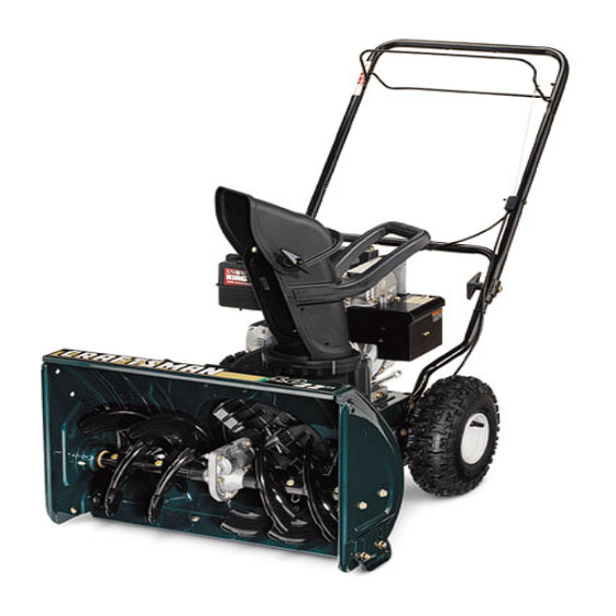
SAFETY RECALL
CHECK YOUR TWO STAGE COMPACT
SNOW THROWER TO SEE IF IT IS RECALLED...
Over inflating the tire with excessive pressure (well above 20 PSI) may
cause the plastic wheel rims to explode posing a risk of serious injury.
8 AM and 5 PM EST Monday through Friday.
IMPORTANT!
If you have already received and installed the Recall Kit which includes two
Pressure Relief Valves, two Warning labels, and installation instructions (Form # 769-02127,
769-02722 or 769-02723), please disregard this notice.
In cooperation with the U.S. Consumer Product Safety Commission
31A-3BAD762 and 31AS3DDE729
Sold between July 2004 and March 2006
________________________________
Do not inflate tires!
CALL
Customer Service toll free between
1-888-848-6038
Yard Machine Models Affected
31A-3AAD700, 31A-3BAD700,
31A-3BAD729, 31A-3BAD752,
Troy-Bilt Models Affected
31AS3BB2766
Craftsman Models Affected
247.88255 (31A-3BDE799)
Sold between July 2004 and March 2006
247.88700 (31AS3AAD799)
Sold between July 2005 and March 2006
Form No. 769-04961
Advertisement

Related Manuals for MTD Troy-Bilt 3BB


Summary of Contents for MTD Troy-Bilt 3BB
- Page 1 SAFETY RECALL CHECK YOUR TWO STAGE COMPACT SNOW THROWER TO SEE IF IT IS RECALLED… Yard Machine Models Affected 31A-3AAD700, 31A-3BAD700, 31A-3BAD729, 31A-3BAD752, 31A-3BAD762 and 31AS3DDE729 Troy-Bilt Models Affected 31AS3BB2766 Sold between July 2004 and March 2006 ________________________________ Craftsman Models Affected 247.88255 (31A-3BDE799) Sold between July 2004 and March 2006 247.88700 (31AS3AAD799)
- Page 2 Operator’s Manual Two-Stage Snow Thrower Model 3BB IMPORTANT: Read safety rules and instructions carefully before operating equipment. Warning: This unit is equipped with an internal combustion engine and should not be used on or near any unimproved forest- covered, brush-covered or grass-covered land unless the engine’s exhaust system is equipped with a spark arrester meeting applicable local or state laws (if any).
- Page 3 TABLE OF CONTENTS Content Page Content Page Important Safe Operation Practices Maintaining Your Snow Thrower Assembling Your Snow Thrower Servicing Your Snow Thrower Know Your Snow Thrower Trouble Shooting Operating Your Snow Thrower Illustrated Parts Making Adjustments Warranty FINDING MODEL NUMBER This Operator’s Manual is an important part of your new snow thrower.
- Page 4 SECTION 1: IMPORTANT SAFE OPERATION PRACTICES WARNING: This symbol points out important safety instructions which, if not followed, could endanger the personal safety and/or property of yourself and others. Read and follow all instructions in this manual before attempting to operate this machine. Failure to comply with these instructions may result in personal injury.
- Page 5 Never run an engine indoors or in a poorly ventilated Before cleaning, repairing, or inspecting machine area. Engine exhaust contains carbon monoxide, an disengage all control levers and stop the engine. Wait odorless and deadly gas. until the auger/impeller come to a complete stop. Do not operate machine while under the influence of Disconnect the spark plug wire and ground against the alcohol or drugs.
- Page 6 SECTION 2: ASSEMBLING YOUR SNOW THROWER This unit is shipped with the engine full of IMPORTANT: oil. After assembly, see page 8 for fuel and oil details. Handle Knob Removing From Carton Saddle Washer • Cut the corners of the carton and lay the sides flat on the ground.
- Page 7 Final Adjustments Check the adjustments as instructed and IMPORTANT: make any final adjustments necessary before operating the unit. Check all nuts and bolts for tightness.Failure to High Position follow these instructions may cause damage to unit. Middle Position Tire Pressure (Pneumatic Tires) Low Position The tires are over-inflated for shipping purposes.
- Page 8 SECTION 3: KNOW YOUR SNOW THROWER WARNING: Be familiar with all the controls on the snow thrower and their proper operation. Know how to stop the machine and disengage them quickly. • Compare Figure 6 with your equipment and follow description of controls, given below, to get familiar with their operation.
- Page 9 SECTION 4: OPERATING YOUR SNOW THROWER Before Starting Engine Electric Starter This snow thrower is equipped with a 120 volt A.C. Engine Oil electric starter. This electric starter, with a three-wire The engine is shipped with oil in it. Check the oil level power cord and plug, is designed to operate on 120 volt before first use.
- Page 10 Before Stopping NOTE: When engaging the electric starter, a slight hesitation of a few seconds may occur before the • Run engine for a few minutes to help dry off any engine starts to turn. This is normal and is not harmful moisture on engine.
- Page 11 Operating Tips • Allow the auger to remain engaged for approximately ten (10) seconds before releasing • For most efficient snow removal, remove snow the auger control. Repeat this several times. immediately after it falls. • With the engine running in the FAST position and •...
- Page 12 Skid Shoe • Remove the self-tapping screw and press the tabs that secure the belt cover to the snow thrower The space between the shave plate and the ground housing. Pull the belt cover from around the engine can be adjusted. For close snow removal, place skid and chute and keep it away.
- Page 13 • With engine on level ground, oil must be to FULL • Check and make sure that the level of oil is up to mark on dipstick. See Figure 10. the FULL mark on the dipstick. • Stop engine and wait several minutes before Service Spark Plug checking oil level.
- Page 14 Replacing Belts • Tip the snow thrower up and forward so that it rests on the auger housing. • Remove the spring that connects the transmission NOTE: There are two belts on this snow thrower: auger to a bolt on the engine frame. See Figure 15. belt and drive belt.
- Page 15 Off-Season Storage • Remove all debris from the exterior of equipment. • Follow lubrication recommendations on page 11. • Always store the snow thrower in a clean, dry area. WARNING: Never store engine with fuel in NOTE: When storing any type of power equipment in an tank indoors or in poorly ventilated areas, unventilated or metal storage shed, care should be where fuel fumes may reach an open flame,...
- Page 16 SECTION 9: PARTS LIST FOR MODEL 3BB Ref. No. Part No. Description Ref. No. Part No. Description 710-0449 Carriage Screw 5/16-18 x 2.25” 711-1364 Clevis Pin 710-0605 Mach. Screw 1/4-20 x 1.825” 738-1231 Axle 710-0726 Screw, 5/16-12 x.75” 736-0242 Bell Washer 714-0115 Cotter Pin, 1/8 x 1.0 712-04064...
- Page 17 Model 3BB Shown for reference only Shown for reference only...
- Page 18 Model 3BB Ref. No. Part No. Description 710-0654A TT Sems Screw 3/8-16 x 1.0” 710-0696 Hex Bolt 3/8-24 x 0.875” 710-1245B Lock Bolt 5/16-24 x 0.875” — Engine 736-0242 Bell Washer,.340 x.872 x.060 736-0247 Flat Washer,.406ID x 1.25OD 736-0331 Bell Washer,.390 x 1.13 x.062 736-0505 Flat Washer,.34ID x 1.50OD 736-0507...
- Page 19 Model 3BB Shown for reference only...
- Page 20 Model 3BB Ref. No. Part No. Description Ref. No. Part No. Description 684-04037 Chute Assembly 715-04020 Spiral Pin 710-04071 Carriage Bolt 5/16-18 x 1.0” 721-0327 Oil Seal 710-0451 Carriage Bolt 5/16-18 x 0.750” 741-0662 Flange Bearing 712-04063 Flange Lock Nut, 5/16-18 736-3084 Flat Washer,.51 x 1.12 x.06 720-0284...
- Page 21 MANUFACTURER’S LIMITED WARRANTY FOR: The limited warranty set forth below is given by Troy-Bilt LLC Troy-Bilt does not extend any warranty for products with respect to new merchandise purchased and used in the sold or exported outside of the United States, its United States, its possessions and territories.
- Page 22 Operator’s Manual Two-Stage Snow Thrower Model 3BB IMPORTANT: Read safety rules and instructions carefully before operating equipment. Warning: This unit is equipped with an internal combustion engine and should not be used on or near any unimproved forest- covered, brush-covered or grass-covered land unless the engine’s exhaust system is equipped with a spark arrester meeting applicable local or state laws (if any).
- Page 23 TABLE OF CONTENTS Content Page Content Page Important Safe Operation Practices Maintaining Your Snow Thrower Assembling Your Snow Thrower Servicing Your Snow Thrower Know Your Snow Thrower Trouble Shooting Operating Your Snow Thrower Illustrated Parts Making Adjustments Warranty FINDING MODEL NUMBER This Operator’s Manual is an important part of your new snow thrower.
- Page 24 SECTION 1: IMPORTANT SAFE OPERATION PRACTICES WARNING: This symbol points out important safety instructions which, if not followed, could endanger the personal safety and/or property of yourself and others. Read and follow all instructions in this manual before attempting to operate this machine. Failure to comply with these instructions may result in personal injury.
- Page 25 Never run an engine indoors or in a poorly ventilated Before cleaning, repairing, or inspecting machine area. Engine exhaust contains carbon monoxide, an disengage all control levers and stop the engine. Wait odorless and deadly gas. until the auger/impeller come to a complete stop. Do not operate machine while under the influence of Disconnect the spark plug wire and ground against the alcohol or drugs.
- Page 26 SECTION 2: ASSEMBLING YOUR SNOW THROWER This unit is shipped with the engine full of IMPORTANT: oil. After assembly, see page 8 for fuel and oil details. Handle Knob Removing From Carton Saddle Washer • Cut the corners of the carton and lay the sides flat on the ground.
- Page 27 Final Adjustments Check the adjustments as instructed and IMPORTANT: make any final adjustments necessary before operating the unit. Check all nuts and bolts for tightness.Failure to High Position follow these instructions may cause damage to unit. Middle Position Tire Pressure (Pneumatic Tires) Low Position The tires are over-inflated for shipping purposes.
- Page 28 SECTION 3: KNOW YOUR SNOW THROWER WARNING: Be familiar with all the controls on the snow thrower and their proper operation. Know how to stop the machine and disengage them quickly. • Compare Figure 6 with your equipment and follow description of controls, given below, to get familiar with their operation.
- Page 29 SECTION 4: OPERATING YOUR SNOW THROWER Before Starting Engine Electric Starter This snow thrower is equipped with a 120 volt A.C. Engine Oil electric starter. This electric starter, with a three-wire The engine is shipped with oil in it. Check the oil level power cord and plug, is designed to operate on 120 volt before first use.
- Page 30 Before Stopping NOTE: When engaging the electric starter, a slight hesitation of a few seconds may occur before the • Run engine for a few minutes to help dry off any engine starts to turn. This is normal and is not harmful moisture on engine.
- Page 31 Operating Tips • Allow the auger to remain engaged for approximately ten (10) seconds before releasing • For most efficient snow removal, remove snow the auger control. Repeat this several times. immediately after it falls. • With the engine running in the FAST position and •...
- Page 32 Skid Shoe • Remove the self-tapping screw and press the tabs that secure the belt cover to the snow thrower The space between the shave plate and the ground housing. Pull the belt cover from around the engine can be adjusted. For close snow removal, place skid and chute and keep it away.
- Page 33 • With engine on level ground, oil must be to FULL • Check and make sure that the level of oil is up to mark on dipstick. See Figure 10. the FULL mark on the dipstick. • Stop engine and wait several minutes before Service Spark Plug checking oil level.
- Page 34 Replacing Belts • Tip the snow thrower up and forward so that it rests on the auger housing. • Remove the spring that connects the transmission NOTE: There are two belts on this snow thrower: auger to a bolt on the engine frame. See Figure 15. belt and drive belt.
- Page 35 Off-Season Storage • Remove all debris from the exterior of equipment. • Follow lubrication recommendations on page 11. • Always store the snow thrower in a clean, dry area. WARNING: Never store engine with fuel in NOTE: When storing any type of power equipment in an tank indoors or in poorly ventilated areas, unventilated or metal storage shed, care should be where fuel fumes may reach an open flame,...
- Page 36 SECTION 9: PARTS LIST FOR MODEL 3BB Ref. No. Part No. Description Ref. No. Part No. Description 710-0449 Carriage Screw 5/16-18 x 2.25” 710-0896 Screw, 1/4-14 x.625” 710-0605 Mach. Screw 1/4-20 x 1.825” 711-1364 Clevis Pin 710-0726 Screw, 5/16-12 x.75” 738-1231 Axle 736-0242...
- Page 37 Model 3BB Shown for reference only Shown for reference only...
- Page 38 Model 3BB Ref. No. Part No. Description 710-0654A TT Sems Screw 3/8-16 x 1.0” 710-0696 Hex Bolt 3/8-24 x 0.875” 710-1245B Lock Bolt 5/16-24 x 0.875” — Engine 736-0242 Bell Washer,.340 x.872 x.060 736-0247 Flat Washer,.406ID x 1.25OD 736-0331 Bell Washer,.390 x 1.13 x.062 736-0505 Flat Washer,.34ID x 1.50OD 736-0507...
- Page 39 Model 3BB Shown for reference only...
- Page 40 Model 3BB Ref. No. Part No. Description Ref. No. Part No. Description 684-04037 Chute Assembly 715-04020 Spiral Pin 710-04071 Carriage Bolt 5/16-18 x 1.0” 721-0327 Oil Seal 710-0451 Carriage Bolt 5/16-18 x 0.750” 741-0662 Flange Bearing 712-04063 Flange Lock Nut, 5/16-18 736-3084 Flat Washer,.51 x 1.12 x.06 720-0284...
- Page 41 MANUFACTURER’S LIMITED WARRANTY FOR: The limited warranty set forth below is given by Troy-Bilt LLC Troy-Bilt does not extend any warranty for products with respect to new merchandise purchased and used in the sold or exported outside of the United States, its United States, its possessions and territories.
Need help?
Do you have a question about the Troy-Bilt 3BB and is the answer not in the manual?
Questions and answers