Advertisement
Quick Links
Safety • Assembly • Operation • Tips & Techniques • Maintenance • Troubleshooting • Parts Lists • Warranty
A
O
AL
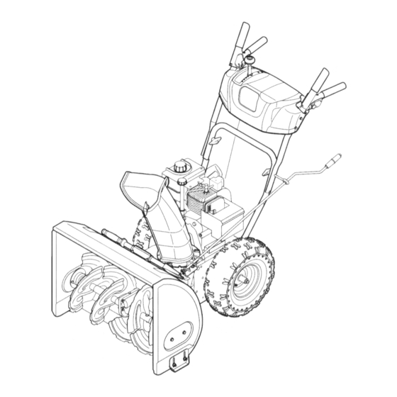
Two-Stage Snow Thrower -- H-Style
iMPORTANT
READ SAFETY
RULES AND iNSTRUCTiONS
CAREFULLY
BEFORE
OPERATION
Warning:
This unit is equippedwith an internal combustionengineand shouldnot be usedon or nearany uniiprovedforest-covered, b rush-
coveredor grass-covered land unlesstheengine'sexhaustsystemis equippedwith a sparkarrestermeetingapplicablelocalor statelaws(if any).
If a sparkarresteris used,it shouldbe maintainedin effectiveworkingorder by the operator.In theState of Californiathe aboveis requiredbylaw
(Section4442 of the CaliforniaPublicResources Code). Otherstatesmay havesimilarlaws.Federallaws applyon federallands.A sparkarrester
for the muffleris availablethroughyour nearestengineauthorizedservicedealeror contactthe servicedepartment,RO. Box361131 Cleveland,
Ohio 44136-0019.
PRINTEDIN U.S.A
MTD LLC, P.O. BOX 361131 CLEVELAND,
OHIO 44136-0019
FORMNO.769-01276C
06/29/2005
Advertisement

Related Manuals for MTD 31AE6FHG705


Summary of Contents for MTD 31AE6FHG705
- Page 1 If a sparkarresteris used,it shouldbe maintainedin effectiveworkingorder by the operator.In theState of Californiathe aboveis requiredbylaw (Section4442 of the CaliforniaPublicResources Code). Otherstatesmay havesimilarlaws.Federallaws applyon federallands.A sparkarrester for the muffleris availablethroughyour nearestengineauthorizedservicedealeror contactthe servicedepartment,RO. Box361131 Cleveland, Ohio 44136-0019. PRINTEDIN U.S.A FORMNO.769-01276C MTD LLC, P.O. BOX 361131 CLEVELAND, OHIO 44136-0019 06/29/2005...
- Page 2 This Operator's Manual is an important part of your new snow thrower, it will help you assemble, prepare and maintain the unit for best performance. Please read and understand what it says. Table of Contents Safety Labels ............Maintaining Your Snow Thrower ...... Safe Operation Practices ........
- Page 3 1. KEEP AWAY FROMROTATING IMPELLER ANDAUGER. C ONTACT WITH IMPELLER OR AUGER CAN AMPUTATE H ANDS ANDFEET. iil _I ii_ _ i _iii_!i _ _ii_ ii USECLEAN-OUT TOOLTOUNCLOG DISCHARGE C HUTE. DISENGAGE CLUTCH L EVERS, STOP ENGINE, ANDREMAIN BEHIND HANDLES U NTIL ALL MOVING PARTS HAVE STOPPED BEFORE UNCLOGGING ORSERVICING MACHINE.
- Page 4 WARNING: Engine Exhaust, some of its constituents, and certain vehicle compo- nents contain or emit chemicals known to State of Californiato cause cancer and birth defects or other reproductiveharm. DANGER: This machine was built to be operated according to the rules for safe operation in this manual.
- Page 5 Operation Maintenance & Storage 1. Donot put hands or feet near rotatingparts, inthe 1. Nevertamper withsafetydevices.Checktheir proper auger/impellerhousingor chuteassembly.Contactwiththe operationregularly.Referto the maintenanceandadjust- mentsectionsof this manual. rotatingparts can amputatehands andfeet. 2. The auger/impellercontrolleveris a safetydevice.Never 2. Beforecleaning,repairing,or inspectingmachinedisen- bypassits operation.Doingso makesthe machineunsafe gageall control leversandstop the engine.Wait untilthe and may causepersonalinjury.
- Page 6 Setting Up Your Snow Thrower 1. Observethe lowerrear area of the snowthrowerto be sure bothcablesare alignedwith rollerguides beforepivotingthe handleupward. NOTE:Reference to right 2. Securethe handleby tighteningthe plasticwing i and left side of the machine knoblocatedon boththe left and rightsidesof the are observedfrom the handle.Removeand discardany rubberbands,if operatingposition.
- Page 7 5. Removethe fiat washerand hairpinclip from theend of the chute directionalcontrol. insertthe end of the chute directionalcontrolinto the lowerbracketand securewith thefiat washerand hair- pin clipjust removed.If necessary,the lowerbracket can be adjusted.Referto ChuteBracketAdjustment. on Page 13. Setting Adjustments Auger Control iMPORTANT: Priorto operatingyoursnowthrower,refer to Auger ControlTeston page 11.Readand followall instructions carefullyand performall adjustmentsto verify your snowthrowerisoperatingsafelyand properly.
- Page 8 Snow Thrower Know Your Shift Lever Drive Control Electric Start Button Operating Chute Assembly Gas Cap Your S"ow \ 0il Fill Th rower CleanOut Tool Engine Controls Recoil Starter Handle ElectricStarter 0utlet / Primer ___ I ///I ignition WARNING Choke/ Control Read, understand, Angers...
- Page 9 Auger Control Ignition The ignition keyisa safety devise.It mustbe fully insertedin orderfor the engineto start. Removethe ignition key whenthe snowthrowerisnot inuse. NOTE:Do notturn the ignitionkey in an attemptto start the engine.Doingso may causeit to break. Clean-Out Tool to clear a clogged chute assem- WARNING"...
- Page 10 6. Asthe enginewarms,slowlyrotatethe chokecontrol Gas & Oil Fill-Up to the OFFposition.If the enginefalters,quicklyrotate Servicethe enginewith gasolineand oil as instructedin thechokecontrol backto FULLand then slowlyinto theTecumsehEnginesmanualpackedseparatelywith theOFF positionagain. yoursnowthrower.Readinstructionscarefully. 7. Whendisconnectingtheextensioncord, always Starting The Engine unplugtheend at thethree-prongwalloutlet before 1. Attachsparkplug wireto sparkplug. Makecertain the ii!Li i ¸I¸II i unplugging the oppositeend from the snowthrower.
- Page 11 Wipeall snowand moisturefrom thearea aroundthe To Engage Augers engineas wellas the area in and aroundthe drive 1. Toengagetheaugersand start throwingsnow, controland augercontrol.Also,engageand release squeezethe augercontrolagainstthe left handle. bothcontrolsseveraltimes. Releaseto stopthe augers. NOTE: Keepthe keyin a safe place.Theenginecannot When selecting a Auger Control Test startwithoutthe ignitionkey.
- Page 12 Auger Control Toadjustthe augercontrol,referto page 13. Shift Cable If the full rangeof speeds(forwardand reverse)cannot be achieved,referto thefigureto the left and adjustthe shiftcable asfollows: 1. Placethe shiftleverin the fastest forward speed position. 2. Loosenthe hex nuton the shiftcable indexbracket. See Figure3. 3.
- Page 13 Drive Control Whenthe drivecontrolis releasedand inthe disengaged "up" position,thecable shouldhavevery little slack.It shouldNOT be tight. Checkthe adjustmentof thedrivecontrol as follows: 1. With the drivecontrol released,pushthe snowthrower gently forward.The unitshouldroll freely. 2. Engagethe drivecontroland gentlyattemptto push the snowthrowerforward.The wheelsshouldnotturn. The unit shouldnot roll freely. 3.
- Page 14 Engine Referto the separate Tecumseh Enginesmanual packedwith your unitfor all enginemaintenance. Lubrication Engine Maintaining Referto the separate Tecumseh Enginesmanual packedwith your unitfor all enginelubricationinstruc- tions. Your Snow Gear Shaft Thegear (hex) shaftshouldbe lubricatedat least once a seasonor after every25 hoursof operation. 1.
- Page 15 Auger Belt Replacement To removeand replaceyoursnow thrower'sauger belt, proceedas follows: 1. Removethe plasticbelt coveron the front of the engineby removingthe two self-tappingscrews. NOTE:Drainthe gasolinefrom the snowthrower,or ntaining placea pieceof plasticunderthe gas cap. C re,u,y p,vo, s oow up Your Snow that it restson the augerhousing.Removethe frame coverfrom the undersideof the snow throwerby removingfour self-tappingscrewswhich secureit.
- Page 16 Augers * Theaugersare securedto the spiralshaftwith two shearpinsand cotterpins. If the augershouldstrikea foreignobject or icejam,the snowthroweris designed so that the pinsmay shear.Referto Figure9. If theaugerswill notturn, checkto seeifthe pinshave "'tii lv=a=n a n ng sheared.One set of replacement s hearpins hasbeen providedwith the snowthrower.When replacingpins, sprayan oil lubricantintoshaft beforeinserting n ew pins.
- Page 17 Friction Wheel Removal If the snowthrowerfails to drivewith the drivecontrol engaged,and performingthedrivecontrol cableadjust- menton page 14fails to correctthe problem,the friction wheelmay needto be replaced.Followthe instructions below.Examinethe frictionwheelfor signsof wearor crackingand replaceif necessary • Placethe shiftleverin third Forward(F3) position. • Drainthe gasolinefrom the snowthrower,or placea pieceof plasticunderthe gas cap.
- Page 18 If the snowthrowerwill not be usedfor30 daysor longer, Removeall gasolinefrom thecarburetorand the fuel or if it is the end of the snow seasonwhenthe last pos- tank to preventgumdepositsfromformingon these sibilityof snow is gone,the equipmentneedsto be stored partsand harmingtheengine. properly.Followstorageinstructionsbelowto ensuretop Runthe engineuntilthe fuel tank is emptyand it stops performance from the snowthrowerfor many moreyears.
- Page 19 4. Carburetoroutof adjustment. 4. Contact MTDServiceCenter. further details, Contact aMTD authorized service center or call Engine overheats 1 carburetor notadjustedproperly, li Contact MTD serViCe Center: 1(800) 800-7310for assistance Excessive 1. Looseparts or damagedauger. Stop engineimmediately and Vibration disconnectsparkplug wire.Tighten all bolts and nuts.If vibration continues,haveunit servicedby a MTDServiceCenter.
- Page 20 Style H...
- Page 21 731-2635 SnowRemoval T oolMount 29. 684-04107 SpiralAssembly,LH 684-04057 ImpellerAssembly,12"Dia. 30. 684-04108 SpiralAssembly,RH 710-0347 Hex Screw,3/8-16,1.75,Gr5 31. 731-04870" Spacer,1.25ODx.75 ID x 1.00 32. 736-0188 Washer,Fiat,.76x 1.49x .06 710-0451 Bolt, Carriage,5/16-18,.750Grl 710-0604A Screw, 5/16-18,0.625 33. 741-0493A Bushing,Flange,.80 ID x .91OD 710-0703 Screw,Carriage,1/4-20,.750,Gr5 34.
- Page 22 Style H...
- Page 23 631-04133 HandleAssembly,Lock,LH 30. 736-0185 Washer,Fiat,.375x .738x .063 631-04134A HandleAssembly,Lock,RH 31. 736-0451 Washer,Saddle,320 x .93x .060 684-04105A HandleAss' y, Engagement L H 32. _ 747-04263 _ Eye Bolt,Chute Crank 33. 749-04138 Handle,Lower 684-04106A HandleAss'y,Engagement,RH 710-0224 Screw,#10-16,0.500 34. 749-04141 Handle,Upper,RH 710-1026 Screw,1/4-20,1.750 35.
- Page 24 Style H...
- Page 25 756-04177 Disc, FrictionWheel 37. 731-04873 Spacer,1.25x .75x 3.0 684-04153 FrictionWheelAssembly,5.50D 38. 738-04168 Axle, .75x 22" 684-04154 SupportBracket,FrictionWheel 39. 741-0919 Ball Bearing 40. 710-0106 Hex Screw,1/4-20,1.25,Gr5 684-04156 Shift Assembly,Rod 710-0627 Hex Screw,5/16-24,.750,Gr5 41. 710-0191 Hex Screw,3/8-24, 1.25,Gr8 710-0788 Screw,1/4-20,1.000 42. 710-0672 Hex Screw,5/16-24,1.25,Gr5 710-0896 Screw,1/4-14x .625...
- Page 26 NOTES...
- Page 27 NOTES...
- Page 28 To locate the dealer in your area, check your Yellow Pages, or lasts, so the aboveexclusionsor limitationsmay notapplyto you. contact MTD LLC at RO. Box 361131,Cleveland, Ohio 44136-0019,or In no eventshall recoveryof any kind be greaterthan theamountof the call 1-800-800-7310 or 1-330-220-4683 or log on to our Web site at purchasepriceof the productsold.
Need help?
Do you have a question about the 31AE6FHG705 and is the answer not in the manual?
Questions and answers