
Related Manuals for Econ 79653


Summary of Contents for Econ 79653
- Page 1 Installation & Operation Manual Proven Quality since 1892 ECON Ex-d and Ex-i Limit Switch Box Fig. 79653 Scan for manual Installation & Operation Manual for Limit Switch Box : Fig. 79653 ECON limit switch Fig. 79653 www.eriks.com Rev.1...
- Page 2 Mechanical switch – 2SPDT with CPT, Current position Transmitter (optional) 8.6 Settings of the Current Position transmitter unit – CPT (Optional) 8.6.1 Calibration of the potentiometer 8.6.2 Calibration of the zero MAINTENANCE TROUBLESHOOTING TOOLS GENERAL INSTALLATION AND MAINTENANCE TIPS ECON limit switch Fig. 79653 www.eriks.com Rev.0...
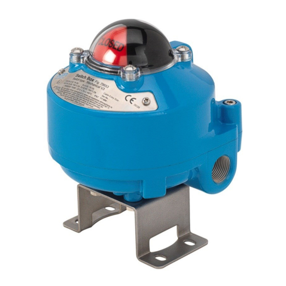
- Page 3 Proven Quality since 1892 INTRODUCTION The ECON Fig. 79653 Ex-d and Ex-i limit switch box is designed to provide accurate and reliable valve position information of actuated valves and hand operated valves. The Fig. 79653 limit switch box consists of an aluminium body a polycarbonate visual position indicator, quick-set cam assemblies, terminal strip, switch assemblies and an easy mounting bracket.
- Page 4 Aluminium Die Casting Captive Cover Bolt Stainless steel Name Plate Stainless steel Shaft Stainless steel Switch See switch type specification (chapter 3) Body Aluminium Die casting Terminal Strip 8 positions Grounding Lug Stainless steel ECON limit switch Fig. 79653 www.eriks.com Rev.0...
- Page 5 Conduit entries that are not being used must be closed properly by the installer. Certified blanking plugs must be used in order to maintain the explosion and flame proof properties of the limit switch box. ECON limit switch Fig. 79653 www.eriks.com Rev.0...
- Page 6 ECON limit switch boxes are supplied with a mounting bracket according to the VDI/VDE 3845 (NAMUR) standard. This standard bracket is selected for actuators with a VDI/VDE connection 30x80 mm and an actuator shaft height of 30mm.
- Page 7 The colour of the cams corresponds with the visual position indicator. Cams can be easily set without using any tools. ECON cams have a spline connection and can be set by lifting or pushing down the cams over the shaft . The cams are spring loaded and therefore self-locking.
- Page 8 A wiring diagram, located inside the cover, indicates which terminal numbers correspond with switch contacts. Follow the wiring diagram in order to make a correct connection to your system. A solenoid valve may also be wired through the ECON limit switch box. Two auxiliary terminals (EXT) are included as a standard.
- Page 9 Installation & Operation Manual Proven Quality since 1892 8.5.3 Proximity switch - P&F NBB3-V3-Z4 8.5.4 Proximity switch - P&F NBB2-V3-E2 ECON limit switch Fig. 79653 www.eriks.com Rev.0...
- Page 10 8.5.6 Mechanical switch - 2 SPDT with CPT, Current Position Transmitter (Optional) Note: The limit switch box must be grounded at all times. At least a 2 sq. mm wire is recommended for grounding. ECON limit switch Fig. 79653 www.eriks.com Rev.0...
- Page 11 Operate the actuator to the middle position and thereafter to the fully closed position. As soon as the actuator reaches the fully closed position, adjust the “zero” rotary switch on the P CB until a value of 20mA is achieved. ECON limit switch Fig. 79653 www.eriks.com Rev.0...
- Page 12 Installation & Operation Manual Proven Quality since 1892 MAINTENANCE The ECON Fig. 79653 limit switch box is designed to provide accurate and reliable valve position signalling and indicating of most automated valves. WARNING: Inspection and maintenance work must be performed by qualified and trained pe rsonnel ...
- Page 13 If defects are found during maintenance, repair measures must be taken immediately. Sealing surfaces must not be coated. Parts may only be exchanged by genuine parts. ECON limit switch Fig. 79653 www.eriks.com Rev.0...
Need help?
Do you have a question about the 79653 and is the answer not in the manual?
Questions and answers