
Related Manuals for Econ 79650


Summary of Contents for Econ 79650
- Page 1 Installation & Operation Manual Proven Quality since 1892 ECON Limit Switch Box All Stainless Steel Enclosure Fig. 79650 Scan for manual Installation & Operation Manual for Limit Switch Box: Fig. 79650 ECON Limit Switch Box Fig. 79650 www.eriks.com Rev.0...
- Page 2 Mechanical switch - 2 SPDT (Standard) 8.4.2 Proximity switch - P&F NBB2-V3-Z4L 8.4.3 Proximity switch - P&F NBB2-V3-E2 MAINTENANCE 10. TROUBLE SHOOTING 11. TOOLS 12. GENERAL INSTALLATION AND MAINTENANCE TIPS 13. DIMENSIONS ECON Limit Switch Box Fig. 79650 www.eriks.com Rev.0...
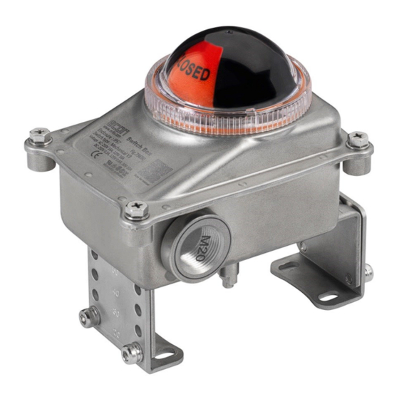
- Page 3 Proven Quality since 1892 INTRODUCTION The ECON Fig. 79650 limit switch box is designed to provide accurate and reliable valve position information of actuated valves and also hand operated valves. The Fig. 79650 limit switch box consists of an press-formed stainless steel body, a poly carbonate visual position indicator, quick-set cam assemblies, terminal strip, switch assemblies and an easy mounting bracket.
- Page 4 Remove the packing wrap or cardboard box carefully. Inspect the product for any physical damage that may have occurred during shipment. • Check the product specification of the received product. If a wrong product has been supplied, please immediately report this to the distributing company. ECON Limit Switch Box Fig. 79650 www.eriks.com Rev.0...
- Page 5 The colour of the cams corresponds with the visual position indicator. Cams can be easily set without using any tools. ECON cams have a spline connection and can be set by lifting or pushing down the cams over the shaft . The cams are spring loaded and therefore self-locking.
- Page 6 A wiring diagram, located inside the cover, indicates which terminal numbers correspond with switch contacts. Follow the wiring diagram in order to make a correct connection to your system. A solenoid valve may also be wired through the ECON limit switch box. Two auxiliary terminals (EXT) are included as a standard.
- Page 7 Installation & Operation Manual Proven Quality since 1892 8.4.1 Mechanical switch – 2 SPDT (Standard) 8.4.2 Proximity switch - P&F NBB2-V3-Z4L ECON Limit Switch Box Fig. 79650 www.eriks.com Rev.0...
- Page 8 Proven Quality since 1892 8.4.3 Proximity switch - P&F NBB2-V3-E2 Note: The limit switch box must be grounded at all times. At least a 2 sq. mm wire is recommended for grounding. ECON Limit Switch Box Fig. 79650 www.eriks.com Rev.0...
- Page 9 Installation & Operation Manual Proven Quality since 1892 MAINTENANCE The ECON Fig. 79650 limit switch box is designed to provide accurate and reliable valve position signalling and indicating of most automated valves. WARNING: Inspection and maintenance work must be performed by qualified and trained personnel ...
- Page 10 If defects are found during maintenance, repair measures must be taken immediately. Sealing surfaces must not be coated. Parts may only be exchanged by genuine parts. ECON Limit Switch Box Fig. 79650 www.eriks.com Rev.0...
- Page 11 Installation & Operation Manual Proven Quality since 1892 13 DIMENSIONS 12.1 Bracket type (Optional) : 80X30 H20, 80X30 H30, 130X30 H30 or 130X30 H50 ECON Limit Switch Box Fig. 79650 www.eriks.com Rev.0...
Need help?
Do you have a question about the 79650 and is the answer not in the manual?
Questions and answers