Advertisement
Quick Links
Description
iGX100L 200 V – 230 V 50/60 Hz
iGX100L 380 V – 460 V 50/60 Hz
iGX100L 200 V – 230 V 50/60 Hz SS
iGX100L 380 V – 460 V 50/60 Hz SS
iGX600L 200 V – 230 V 50/60 Hz
iGX600L 380 V – 460 V 50/60 Hz
iGX600L 200 V – 230 V 50/60 Hz SS
iGX600L 380 V – 460 V 50/60 Hz SS
iGX100N 200 V – 230 V 50/60 Hz
iGX100N 380 V – 460 V 50/60 Hz
iGX100N 200 V – 230 V 50/60 Hz SS
iGX600N 200 V – 230 V 50/60 Hz
iGX600N 380 V – 460 V 50/60 Hz
Instruction Manual
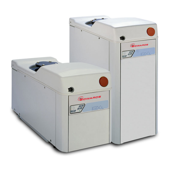
iGX Dry Pumping Systems
Item Number
A546-10-958
A546-10-959
A548-10-958
A548-10-959
A546-30-958
A546-30-959
A548-30-958
A548-30-959
A546-11-958
A546-11-959
A548-11-958
A546-31-958
A546-31-959
Description
iGX1000N 200 V – 230 V 50 Hz
iGX1000N 380 V – 460 V 50 Hz
iGX1000N 200 V – 230 V 50/60 Hz SS
iGX1000N 200 V - 230 V 50/60 Hz SS
iGX100M 200 V – 230 V 50/60 Hz
iGX100M 380 V – 460 V 50/60 Hz
iGX100M 200 V – 230 V 50/60 Hz SS
iGX100MTi 200 V – 230 V 50/60 Hz
iGX100MTi 380 V – 460 V 50/60 Hz
iGX100MTi 200 V – 230 V 50/60 Hz SS
iGX100MTi 200 V – 230 V 50/60 Hz SS
iGX600M 200 V – 230 V 50/60 Hz
iGX600M 380 V – 460 V 50/60 Hz
iGX600M 200 V – 230 V 50/60 Hz SS
iGX600M 200 V – 230 V 50/60 Hz SS
A546–00–880
Issue E Original
Item Number
A546-81-958
A546-81-959
A548-81-958
A543-81-958
A546-12-958
A546-12-959
A548-12-958
A546-48-958
A546-48-959
A548-48-958
A543-48-958
A546-32-958
A546-32-959
A548-32-958
A543-32-958
Advertisement

Subscribe to Our Youtube Channel
Related Manuals for Edwards iGx

Summary of Contents for Edwards iGx
- Page 1 A546–00–880 Issue E Original Instruction Manual iGX Dry Pumping Systems Description Item Number Description Item Number iGX100L 200 V – 230 V 50/60 Hz A546-10-958 iGX1000N 200 V – 230 V 50 Hz A546-81-958 iGX100L 380 V – 460 V 50/60 Hz A546-10-959 iGX1000N 380 V –...
- Page 2 Declaration of Conformity Edwards Limited, Crawley Business Quarter, Manor Royal, Crawley, West Sussex, RH10 9LW, UK declare under our sole responsibility, as manufacturer and person within the EU authorised to assemble the technical file, that the product(s) iGX100L 200-230V 50/60Hz...
- Page 3 GX Vacuum Pump Range DiHxK Vacuum Pump Range iF Vacuum Pump Range iHxK Vacuum Pump Range DiFxK Vacuum Pump Range iGX Vacuum Pump Range iFxK Vacuum Pump Range EPX Vacuum Pump Range iPX Vacuum Pump Range iQ/QDP/QMB Vacuum Pump Ranges...
- Page 4 This page has been intentionally left blank.
- Page 5 Locate the dry pumping system ..................12 Lubrication ....................... 13 Connect the iGX system to the vacuum/exhaust system and interstage connection (if fitted) ....13 Connect to the factory extraction system (optional) .............14 Connect the nitrogen supply (if provided) ................14 3.5.1...
- Page 6 Installing 3/8" quick connect fittings (provided) ..............20 Gas module access panel ....................21 Flow tube (14 slm) ......................21 Flow tube (4 slm) .......................22 Page ii © Edwards Limited 2014. All rights reserved. Edwards and the Edwards logo are trade marks of Edwards Limited.
- Page 7 Publication number Vacuum pump and vacuum system safety P400–40–100 Trademark credits ® Fomblin is a registered trademark of Ausimont SpA. © Edwards Limited 2014. All rights reserved. Page iii Edwards and the Edwards logo are trade marks of Edwards Limited.
- Page 8 A546–00–880 Issue E This page has been intentionally left blank. Page iv © Edwards Limited 2014. All rights reserved. Edwards and the Edwards logo are trade marks of Edwards Limited.
- Page 9 Introduction Scope and definitions This manual provides installation, operation and maintenance instructions for the Edwards iGX dry pumping systems. The pump must be used as specified in this manual. Read this manual before installing and operating the pump. Important safety information is highlighted as WARNING and CAUTION instructions; these instructions must be obeyed.
- Page 10 If using the iGX system on an application for which it is not suitable (refer to Figure 1), the warranties may invalidate. If in doubt, contact Edwards for advice as to the suitability of the iGX system for any particular application. Figure 1 - iGX Applications chart The iGXL system...
- Page 11 Gas Module access panel Exhaust gas outlet connection Comms 3 Ethernet Extraction port Nitrogen purge port Leak-test port connection not on T variants © Edwards Limited 2014. All rights reserved. Page 3 Edwards and the Edwards logo are trade marks of Edwards Limited.
- Page 12 Figure 4). Only one of these can have control of the iGX system at any one time. That is, once one of these has control of the iGX system, control requests from the other are denied. The PDT indicates who is in control. LEDs are also provided on the rear panel, front panel or PDT, which illuminate to indicate 'in control'.
- Page 13 Active utility control Active Utility Control (AUC) is available on the iGX system. This function reduces the power of the iGX system while on stand-by. The power reduction is achieved by reducing the rotational speed of the iGX pump. This function also reduces the nitrogen purge of M variant systems while in stand-by mode.
- Page 14 A546–00–880 Issue E This page has been intentionally left blank. Page 6 © Edwards Limited 2014. All rights reserved. Edwards and the Edwards logo are trade marks of Edwards Limited.
- Page 15 Mass flow transducer accuracy Interstage (I) Peak pumping speed, interstage Ultimate, interstage mbar Pump interstage flange NW16 NW16 © Edwards Limited 2014. All rights reserved. Page 7 Edwards and the Edwards logo are trade marks of Edwards Limited.
- Page 16 Table 4 - Centre of gravity and levelling foot loads (Refer to Figure 6) 1000 Centre of gravity Levelling foot loads Figure 6 - Centre of gravity and levelling foot loads Page 8 © Edwards Limited 2014. All rights reserved. Edwards and the Edwards logo are trade marks of Edwards Limited.
- Page 17 30 V d.c. 1 A closed 5 - Normally open and 6 - common 60 V d.c. 0.5 A Not on T variant © Edwards Limited 2014. All rights reserved. Page 9 Edwards and the Edwards logo are trade marks of Edwards Limited.
- Page 18 °C Storage -45 to +55 °C Relative humidity 10 to 90 Maximum operating altitude 2000 Pollution degree 2 (IEC 61010) Page 10 © Edwards Limited 2014. All rights reserved. Edwards and the Edwards logo are trade marks of Edwards Limited.
- Page 19 Detailed safety information is given in Edwards Publication Number P400-40-100 'Vacuum Pump and Vacuum System Safety'. Only Edwards engineers may install the dry pumping system. Users can be trained by Edwards to conduct the tasks described in this manual, contact the local service centre or Edwards for more information.
- Page 20 2. Adjust the levelling feet (24) to make sure that the iGX system is level and is not supported by the castors. The lifting eyebolt must be retained for future use with this system.
- Page 21 loads anticipated. Lubrication The iGX system is given a charge of oil before it leaves the factory. There is no requirement to check and adjust the oil level. Connect the iGX system to the vacuum/exhaust system and interstage connection (if fitted)
- Page 22 Refer to Figure 2, items 16, 18 and 27. Use the following procedure to connect the inlet and exhaust of the iGX system to the vacuum inlet and exhaust pipeline: 1. Remove the temporary cover or blanking plate from the inlet of the iGX system. Retain the nuts, bolts, washers and blanking plate for future use.
- Page 23 Note: If further information on leak testing is needed, look it up on the Edwards website at www.edwardsvacuum.com, or contact the supplier or Edwards for advice. Refer to Figure 2, item 28.
- Page 24 2, item 2. Use the following procedure to connect the electrical supply to the iGX system. When making the electrical supply cable, ensure that the earth (ground) conductor is longer than the phase conductors. This will ensure that if the cable is accidentally dragged and the strain relief bush on the electrical supply connector mating-half fails, the earth (ground) conductor will be the last conductor to be pulled from the connector.
- Page 25 Tighten the connection using a flat blade screwdriver. 6. Refit the cover to the connector block, then tighten the strain relief bush. 7. Connect the mating half to the electrical supply connector of the iGX system (Figure 2, item 2).
- Page 26 - refer to the Technical Data section for pump system rating. Connect an additional RF earth (ground) (optional) If the iGX system will be operated in an area subject to high RF (radio frequency) emissions, in accordance with good RF installation practice, Edwards recommends:...
- Page 27 (Figure 2, item 11) on the rear of the iGX system. If not, the iGX system will not be able to operate. If required, connect customer supplied control equipment to the iGX system to shut it down in an emergency using...
- Page 28 4, item 5). The green LED will illuminate. Then press the Start button (Figure 4, item 2). 6. If the iGX system starts and continues to operate, continue at Step 7. If a warning or alarm condition is indicated: Shut-down the iGX system: refer to Section 4.3.
- Page 29 A546–00–880 Issue E 7. If the iGX system is an L or M variant, continue at step 8. For N variants, the nitrogen purge flow should be checked as follows; i. Open the gas module access panel by removing the securing screw. Refer to...
- Page 30 If the sensors or microprocessors fail, the total flow rate of nitrogen displayed or output by the iGX system may be incorrect. If the total flow rate of nitrogen to the dry pump for safety reasons needs to be known, fit suitable measurement equipment in the nitrogen supply pipeline.
- Page 31 Press and hold the Start button (Figure 4, item 2) until pumps starts and the Running LED (Figure 4, item 8) is illuminated. © Edwards Limited 2014. All rights reserved. Page 23 Edwards and the Edwards logo are trade marks of Edwards Limited.
- Page 32 If the pump is not going to be required for some time, switch off the electrical supply and the cooling water supply. Page 24 © Edwards Limited 2014. All rights reserved. Edwards and the Edwards logo are trade marks of Edwards Limited.
- Page 33 Automatic shut-down CAUTION If 'Run 'til crash' is selected, the pump(s) can be damaged and any warranties may be invalidated on the iGX system equipment. Normally, if an alarm condition exists, the iGX control system will shutdown the iGX system. If required 'run 'til crash' operation can be requested.
- Page 34 Edwards or refer to the Edwards website. If the emergency stop switch on the front panel has been used to shut down the iGX system, reset the emergency stop switch before restarting the iGX system. Turn the emergency stop switch to reset it, then restart the iGX system...
- Page 35 Particular caution should be exercised when working with Fomblin oil which may have been exposed to temperatures greater than 260 °C. Refer to Edwards Material Safety Data Sheets for detailed information. Ensure that the maintenance technician is familiar with the safety procedures which relate to the products ...
- Page 36 Fluorinated materials in the iGX system may include oils, greases and seals. The iGX system may have overheated if it was misused, if it malfunctioned or if it was in a fire. Edwards Material Safety Data Sheets for fluorinated materials used in the pump are available on request: contact the supplier or Edwards (refer to the address page at the rear of this manual for contact details).
- Page 37 A546–00–880 Issue E If removing the iGX system from its operating location and moving it to another location where maintenance will be performed: 1. Purge the iGX system and shut down the iGX system as described in Section 4 and allow the iGX system to cool down.
- Page 38 Inspect the pump monthly and, if necessary, wipe the outside clean with a soft lint free cloth and a proprietary cleaning material based on demineralised water or isopropanol. Page 30 © Edwards Limited 2014. All rights reserved. Edwards and the Edwards logo are trade marks of Edwards Limited.
- Page 39 Drain the cooling water from the iGX system, if transporting or storing in conditions where the cooling water could freeze. If not, the cooling water may freeze in the iGX system and damage the pump(s) and/or the cooling water pipelines.
- Page 40 A546–00–880 Issue E This page has been intentionally left blank. Page 32 © Edwards Limited 2014. All rights reserved. Edwards and the Edwards logo are trade marks of Edwards Limited.
- Page 41 (refer to forms HS1 and HS2 at the rear of this manual). Do not drain the oil from the iGX pump. Clearly state the pump is full of oil when completing form HS2 Edwards products, spares and accessories are available from Edwards companies in Belgium, Brazil, China, France, Germany, Israel, Italy, Japan, Korea, Singapore, United Kingdom, U.S.A and a world-wide network of distributors.
- Page 42 A507-48-000 Flow control valve 1 lpm (100 only) A507-38-000 2 lpm (3/100, 6/100 and 10/100 only) A507-39-000 PDT holster D372-09-800 Page 34 © Edwards Limited 2014. All rights reserved. Edwards and the Edwards logo are trade marks of Edwards Limited.
- Page 43 Water flow switch kit (Combination) A507-25-000 † iGX Water flow monitor kit A507-26-000 * Not on T variant † ASM required © Edwards Limited 2014. All rights reserved. Page 35 Edwards and the Edwards logo are trade marks of Edwards Limited.
- Page 44 A546–00–880 Issue E This page has been intentionally left blank. Page 36 © Edwards Limited 2014. All rights reserved. Edwards and the Edwards logo are trade marks of Edwards Limited.
Need help?
Do you have a question about the iGx and is the answer not in the manual?
Questions and answers