Advertisement
Quick Links
USER MANUAL
ILC Srl
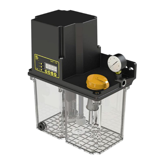
CME
CME series electric gear pump for oil and soft grease
Use in single-line and air+ oil centralised lubrication systems
Translation of original instructions
All ILC products must only be used for their intended purposes, as specified in this brochure and in all instructions. If the product is supplied together with user instructions, the user is required to read
them and comply with them. Not all lubricants are suitable for centralised lubrication systems. ILC lubrication systems or relative components cannot be used together with gas, liquid gas, pressurised
gas in solution and liquids with vapour pressure exceeding normal atmospheric pressure (1013 bar) by more than 0.5 bar, maximum temperature permitted. Any type of dangerous materials, in particular
those classified as such by European Community Directive (EC) 67/548/EEC, Article 2 (2), can only be used in ILC centralised lubrication systems or relative components upon consultation with ILC and
after having received written approval from the company.
Copyright©2018 by I.L.C. Srl
All rights reserved.
I.L.C. srl - Via Garibaldi, 149 - 20155 Gorla Minore - Italy
Phone +39 0331 601697 - Fax +39 0331 365149 - www.ilclube.com - info@ilclube.it
Advertisement

Related Manuals for iLC CME Series

Summary of Contents for iLC CME Series
- Page 1 Translation of original instructions All ILC products must only be used for their intended purposes, as specified in this brochure and in all instructions. If the product is supplied together with user instructions, the user is required to read them and comply with them. Not all lubricants are suitable for centralised lubrication systems. ILC lubrication systems or relative components cannot be used together with gas, liquid gas, pressurised gas in solution and liquids with vapour pressure exceeding normal atmospheric pressure (1013 bar) by more than 0.5 bar, maximum temperature permitted.
- Page 2 TABLE OF CONTENTS Maintenance 1. Introduction 14.1 Maintenance table 2. Application 15. Transport 15.1 Delivery 3. Operating principle 15.2 Storage 4. Technical specifications 16. Operation 5. Installation 16.1 General information 16.2 Commissioning 6. Commissioning 17. Decommissioning 7. Hydraulic diagram 17.1 Temporary decommissioning 8.
- Page 3 Introduction At this point the pressurised lubricant will activate a release 1. Introduction valve, which will discharge the pressure inside the tank and enable the volumetric valves to be filled. This use and maintenance manual refers to the CME pump. Using this pump makes it possible to distribute oil or soft The process repeats each time the motor is switched on and grease in lubrication systems.
- Page 4 Installation network, without creating pipe sections that go up and down. 5. Installation This is in case air enters the distribution lines. Air bubbles tend to rise towards the end of the distribution line and are not Only install the pump in a horizontal position, fastening it to the removed along the way.
- Page 5 Hydraulic diagram 7. Hydraulic diagram pressure switch for controlling the main line gear pump pressure relief valve pressure gauge intake valve release valve electric motor minimum level of lubricant check lubricant loading filter I.L.C. srl - Via Garibaldi, 149 - 20155 Gorla Minore - Italy Phone +39 0331 601697 - Fax +39 0331 602001 - www.ilclube.com - info@ilclube.it...
- Page 6 Connections set up by ILC. pause = the stop period of the pump / operation = the running time of the pump I.L.C. srl - Via Garibaldi, 149 - 20155 Gorla Minore - Italy...
- Page 7 Version with board 9. Version with electronic board An electronic board is installed inside the pump which controls and checks the operation of the entire system. The board is equipped with a display with 4 digits and 4 programming buttons, including the extra-cycle button. In this version, the pump is delivered with level alarm activated (AL-1), oil pressure switch alarm activated (AO-1) and prelube on (the pump starts when it is switched on and operates for the set operating time) PL-1.
- Page 8 Version with board Electrical connections (continued) Connections set up by ILC. For volumetric or air + oil systems. for pulse pause time counted by a switch. pause = the stop period of the pump / operation = the running time of the pump I.L.C.
- Page 9 Version with board Electrical connections (continued) For volumetric or air + oil systems. For pulse pause time counted by a proximity sensor. for air oil systems with air control through a pressure switch. By checking the air pressure switch, the pause cannot be adjusted in pulses.
- Page 10 Modes and programming 10. Operating mode 10.1 Operating Mode In operating mode, the board controls the pump by Function alternating work cycles with pause cycles. The duration Circularly scrolls the menus downwards of the work stage can be configured as time while the duration of the pause can be counted in time (PL Circularly scrolls the menus upwards mode) or in number of pulses, which the board reads...
- Page 11 With E-PM or E-PH are different from 0 E-PS can only be adjusted from 0 to 999. *functions only for air+oil systems exclusively for use by ILC ** pause = the stop period of the pump / operation = the running time of the pump I.L.C.
- Page 12 Air alarm enabling Warmup operating seconds *functions only for air+oil systems exclusively for use by ILC **to be enabled only if a pressure switch to control the air is required I.L.C. srl - Via Garibaldi, 149 - 20155 Gorla Minore - Italy...
- Page 13 Before performing any operation, make sure you have disconnected the power supply. The maintenance table shows the main faults, causes and solutions. If the problem cannot be solved after consulting it, contact the technical office at ILC. 14.1 Maintenance table Symptoms...
- Page 14 Transport 15. Transport The products of I.L.C. Srl are packaged to market standard according to the regulations in force in the country of destination. Proceed with caution during transport. The product must be protected against impact. There are no restrictions for transportation by land, air or sea.
- Page 15 Operation 16. Operation 16.1 General information The pump operates automatically. However, the flow of the lubricant inside the piping must be checked periodically. The filling level of lubricant in the reservoir, being installed, must be visually checked periodically. If an excessively low lubricant level is detected, it must be topped up to the maximum marking as described in the "Commissioning"...
- Page 16 Decommissioning 17. Decommissioning 17.1 Temporary decommissioning Temporary decommissioning of the product described occurs by disconnecting the electrical, pneumatic and/or hydraulic power supply connections. For prolonged product decommissioning, please refer to the information in the "Transport and storage" chapter in these assembly instructions.
- Page 17 Precautions 18. Precautions for use It is necessary to carefully read the warnings on the risks related to using a lubricant pump. The operator must know how it functions and clearly understand the hazards of pumping pressurised lubricants. 18.1 It is recommended to •...
- Page 18 User instructions 19. User instructions Conformity to essential safety requirements and to the provisions in the machinery directive has been checked by filling out the prepared checklists contained in the technical file. 19.1 Lists used • Risk assessment (UNI EN ISO 14121-1). •...
- Page 19 Dimensions 20. Dimensions CME 2L I.L.C. srl - Via Garibaldi, 149 - 20155 Gorla Minore - Italy Phone +39 0331 601697 - Fax +39 0331 602001 - www.ilclube.com - info@ilclube.it...
- Page 20 Dimensions 21. Dimensions CME 3L I.L.C. srl - Via Garibaldi, 149 - 20155 Gorla Minore - Italy Phone +39 0331 601697 - Fax +39 0331 602001 - www.ilclube.com - info@ilclube.it...
- Page 21 Order codes 22. CME order code configurator | - | | - | | - | A (Lubricants) B (Reservoir) C (Control) D (Power supply voltage) Soft grease External control 24 V DC Internal electronics 115 V AC 230 V AC 23.
- Page 22 Spare parts 24. Spare parts Motor cover A70.093732 Motor 24 V DC A94.150311 115 V AC A94.150303 230 V AC A94.150304 Control circuit and timer Without timer (24V DC) A91.111500 Without timer (115/230 V AC) A91.111501 With timer (24V DC) A91.111502 With timer (115 V AC) A91.111503...
- Page 23 Should the warranty still be valid, we will see to repairing or replacing the product at our expense. If the product is not found to be defective, ILC will decide at its discretion whether or not to charge the expenses (logistics).
- Page 24 La società ILC srl, con sede legale in Gorla Minore (VA), Via Garibaldi 149 - ILC srl, registered office in Gorla Minore (VA), Via Garibaldi 149 - ILC srl. au Siège Social à Gorla Minore (VA), Via Garibaldi 149 / ILC srl Gorla Minore (VA), Sitz in Via Garibaldi 149 - La sociedad ILC srl., con sede legal en Gorla Minore (VA), Via Garibaldi 149 - A ILC srl, com sede em Gorla Minore (VA), Via Garibaldi 149...
- Page 25 I.L.C. srl - Via Garibaldi, 149 - 20155 Gorla Minore - Italy Phone +39 0331 601697 - Fax +39 0331 602001 - www.ilclube.com - info@ilclube.it MADE IN ITALY...
Need help?
Do you have a question about the CME Series and is the answer not in the manual?
Questions and answers