Advertisement
Quick Links
TM
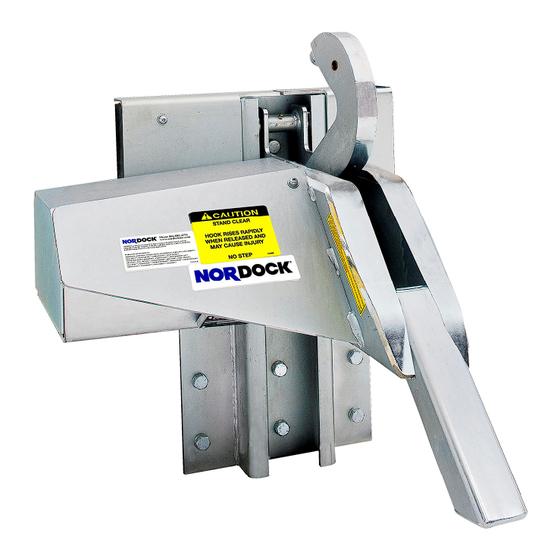
SMART-HOOK
SERIES
AR-10K
Rotating Hook
Vehicle Restraint
Installation & Owner's Manual
This manual applies to model AR-10K restraints manufactured beginning Feb 2018
with serial numbers 41523 and greater (with IP-66 motors)
P/N 59-0052 rev F
N
ORDOCK INC.
Website: nordockinc.com ~ Email: sales@nordockinc.com ~ Toll free: 866-885-4276
Nordock Inc. reserves the right to make changes to specifications without notice or obligation. Nordock products may be covered by
various U.S. and foreign patents or pending applications.
Advertisement

Related Manuals for NORDOCK SMART-HOOK AR-10K


Summary of Contents for NORDOCK SMART-HOOK AR-10K
- Page 1 P/N 59-0052 rev F ORDOCK INC. Website: nordockinc.com ~ Email: sales@nordockinc.com ~ Toll free: 866-885-4276 Nordock Inc. reserves the right to make changes to specifications without notice or obligation. Nordock products may be covered by various U.S. and foreign patents or pending applications.
- Page 3 Contents Contents ....................1 Preface ....................2 Problems, Errors and Omissions ................. 2 Restraint Identification ....................2 Copyright ........................2 Warranty ....................3 Safety Practices ..................4 Labels .......................... 5 Installation .................... 6 Tools Required ......................7 Mounting Requirements ....................7 Installation with Pit Type Levelers................
- Page 4 Restraint Identification It is very important that in order to obtain the best possible service from Nordock Inc., please provide the model and serial number of the restraint whenever you contact us. Below is the same serial number plate that will be found on the left hand hook side plate (standing outside facing the restraint).
- Page 5 Nordock Inc. will at its option within the first year either: 1. Replace the product or the defecteof without charge to the purchaser; or, 2. Alter or repair the product on site or elsewhere, as Nordock Inc. may deem advisable, without charge to the purchaser.
- Page 6 Nordock Inc. Owner’s Manual – SMART-HOOK SERIES - AR-10K Rotating Hook, 59-0052-F Safety Practices The operators of this unit must read these safety practices before installing, operating or servicing the AR-10K restraint. Failure to follow these safety practices may result in bodily injury, property damage or death.
- Page 7 12. If you have any questions, contact your supervisor or your local Nordock Incorporated representative.
- Page 8 Installation WARNING IMPROPER INSTALLATION OF THIS VEHICLE RESTRAINT COULD RESULT IN SERIOUS INJURY OR DEATH TO DOCK WORKERS OR OTHER RESTRAINT USERS A typical AR-10K Rotating Hook restraint installation is shown below. The following installation materials are included with the restraint: 15 pcs.
- Page 9 Docks constructed of other materials require special mounting considerations. Contact your local Nordock distributor for application specific information. 5. Do not install the restraint anchor bolts into concrete of questionable integrity.
- Page 10 Installation with Pit Type Levelers WARNING ALWAYS USE DOCK LEVELER SUPPORT WHEN WORKING UNDER A DOCK LEVELER RAMP OR LIP Place barricades around pit on dock floor and driveway while installing the vehicle restraint The carriage assembly must be removed from the backplate before it is anchored to the wall (refer to the diagram below) Remove the motor and spring covers.
- Page 11 (7) shims 2” wide x 25-5/8” long. (refer to diagram below for placement) If shims need to be more than ½” thick, longer anchors will be required. If the backplate needs to be shimmed out more than 1”, a buildout bracket will be required (Contact Nordock In...
- Page 12 WARNING Improper installation that allows the pendant dock leveler lip to support the weight of the dock leveler could result in serious injury or death. It is sometimes necessary to install lip deflector plates to prevent the possibility of the pendant lip storing on top of or behind the restraint backplate.
- Page 13 CAUTION NEVER weld on the restraint after it has been wired to the control box and the power is on. Damage to the controls or wiring may result. 7. Reinstall the carriage assembly into the backplate weldment. (reference diagram below) a.
- Page 14 WARNING Before doing any electrical work, the power must be disconnected and properly locked/tagged off. Failure to do so could result in death or serious injury. All electrical work must meet all applicable codes and be carried out by a qualified technician.
- Page 15 9. The outside signal light is to be placed approximately 9 ft above the driveway on the driver’s side of the door opening as shown in the diagram below. Drill a hole through the wall at the centre of the signal light mounting position. CAUTIO Mode Capacit...
- Page 16 16. Apply power to the control box and verify correct operation as follows: a. One light must be on, both interior and exterior at all times. b. With the hook in the released position, the exterior light will be solid GREEN and the inside light will be solid RED.
- Page 17 NOTE: If you have any other combination of inside/outside lights, shut the power off to the panel for approximately 10 seconds and then turn it back on. Press the “RELEASE” button and wait for 10 seconds. If the lights do not indicate as specified above, contact the factory at (866) 885-4276 and ask for technical support.
- Page 18 Once the AC power is restored, the battery will begin charging automatically. It takes approximately 72 hours to fully recharge the battery once it has been exhausted. NOTE: To extend battery life, the inside and outside lights will flash when the panel is operating on battery power.
- Page 19 Install the battery in the panel as shown in the adjacent picture. It is positioned top of the metal stand-off post on the bottom left of the panel and the terminals are oriented to the upper right. It is attached to the back and left side of the enclosure with the pre-attached hook and loop fastener strips.
- Page 20 Operation WARNING Before operating or maintaining this truck restraint, read and follow the safety practices contained in this manual. Failure to follow the guidelines in this manual and those in effect in the workplace can result in serious bodily harm and equipment damage.
- Page 21 To Hitch the Truck: 1. Position truck against dock bumpers and set brakes. 2. Press the “LOCK” button on the control panel. The hook will rotate up to engage the truck’s ICC bar. NOTE Visually inspect the vehicle to ensure proper Rear Impact Guard (RIG) engagement by the hook.
- Page 22 NOTE Sometimes during the loading/unloading process, the trailer may “creep” ahead a few inches. This may create a condition with the restraint known as trailer “pinch”. The hook cannot rotate down to the lowered position because it is catching on the corner of the RIG bar which has now moved ahead.
- Page 23 Maintenance Schedule WARNING Before servicing this restraint, read and follow the safety practices contained in this manual. Failure to follow the guidelines in this manual and those in effect in the workplace can result in serious bodily harm and equipment damage. Item Lubrication Inspection...
- Page 24 Parts List Item Description / Model Note Carriage Weldment 52-1053 Roller, Carriage (w/ bearing) 52-1014...
- Page 25 Item Description / Model Note Slope Extension Weldment 52-1013 Clevis Pin, 1" x 4" Steel, Non Plated 13-2658 Washer, 1", Flat, Steel, Plated, SAE 13-2030 Cotter Pin, 3/16" x 1-3/4", Steel, Plated 13-0304 Backplate Weldment 52-1006 Spring Bar 52-1019 Nut, 1/2" Nylock 13-0750 Washer, 1/2"...
- Page 26 Item Description / Model Note Sign, Outside Caution 23-0124 Control Panel, AR-10K, 115V 58-1800 Outside Traffic Light, LED, Red and Green, 10-32 VDC 13-3282 Item Description / Model Note Pushbutton, Flush Face, Yellow 13-1178 Pushbutton, Flush Face, Green 13-1181 Light, Marker, Rectangular, LED, Green, 24 VDC 13-3258 Light, Marker, Rectangular, LED, Red, 24 VDC 13-3427...
- Page 27 Standard Wiring Diagram...
Need help?
Do you have a question about the SMART-HOOK AR-10K and is the answer not in the manual?
Questions and answers