Table of Contents
Advertisement
Advertisement
Table of Contents

Related Manuals for IMO SD1 Series


Summary of Contents for IMO SD1 Series
- Page 1 SD1 Series AC Variable Speed Inverter Drives OPERATION MANUAL...
-
Page 2: Table Of Contents
SD1 Series Inverters Contents Contents Contents ............................ i Chapter 1 Safety Precautions ....................1 1.1 Safety Definition ......................1 1.2 Warning Symbols ......................1 1.3 Safety Guide ........................2 1.3.1 Delivery and installation ..................2 1.3.2 Commissioning & operating .................. 3 1.3.3 Maintenance and component replacement ............ - Page 3 SD1 Series Inverters Contents 3.3.3 STO function installation checklist ..............25 3.4 Layout Protection ......................25 3.4.1 Protecting the inverter and input power cable in short-circuit situations..... 25 3.4.2 Protecting the motor and motor cables ............... 26 3.4.3 Implementing a bypass connection ..............26 Chapter 4 Keypad Operation ....................
- Page 4 SD1 Series Inverters Contents 6.2.3 Inverter faults and solutions ................107 6.2.4 Other states ...................... 114 Chapter 7 Communication Protocol .................. 115 7.1 Modbus Protocol Introduction ..................115 7.2 Application ......................... 115 7.2.1 Two-wire rs485....................115 7.2.2 Rtu mode ......................118 7.2.3 Ascii mode......................
- Page 5 D.2 STO Channel Delay Description ................164 D.3 STO Function Installation Check List ................ 164 Appendix E Further Information ..................166 E.1 Product and Service Inquiries ................... 166 E.2 Feedback of IMO Inverter Manuals ................166 E.3 Documents on the Internet ..................166 -iv-...
-
Page 6: Chapter 1 Safety Precautions
Electrical equipment should be installed, operated, service and maintained only by competent personnel. No responsibility is assumed by IMO Precision Controls Ltd for any consequences arising out of the use of this product. 1.1 Safety Definition... -
Page 7: Safety Guide
SD1 Series Inverters Safety Precautions 1.3 Safety Guide Only qualified electricians are allowed to operate on the inverter. Do not perform any wiring, inspection, or component changes when the power supply is connected. Ensure the power supply is disconnected... -
Page 8: Commissioning & Operating
SD1 Series Inverters Safety Precautions terminals. Please connect the input power cables and motor cables properly; otherwise, the damage to the inverter may occur. 1.3.2 Commissioning & operating Disconnect all power supplies applied to the inverter before the terminal wiring and wait for at least the designated time after disconnecting the power supply. - Page 9 SD1 Series Inverters Safety Precautions When the life cycle ends, the product should enter the recycling system. Dispose of it separately at an appropriate collection point instead of placing it in the normal waste stream.
-
Page 10: Chapter 2 Product Overview
2. Whether the ambient temperature in application is lower than ~10°C. If yes, configure a heating device. Note: If the inverter is installed in a cabinet, the ambient temperature is the air temperature inside the cabinet. 3. When the altitude exceeds 3000m, consult the local IMO dealer or office for details. -
Page 11: Installation Confirmation
SD1 Series Inverters Product Overview When the altitude exceeds 1000m, derate by 1% for every increase of 100m. 4. Whether the ambient humidity is higher than 90% or condensation occurs. If yes, take extra protective measures. 5. Whether there is direct sunlight or biological invasion in the application environment. If yes, take extra protective measures. -
Page 12: Data Related To Safety Standards
SD1 Series Inverters Product Overview 3. Perform commissioning on the machine in jogging mode and check whether the rotating direction of the motor meets the requirement. If no, exchange the wires of any two phases of the motor to change the running direction of the motor. - Page 13 SD1 Series Inverters Product Overview Function Specification Speed control accuracy ±0.2% (SVC) Speed fluctuation ± 0.3% (SVC) Torque response <20ms (SVC) Torque control accuracy 10% Starting torque 0. 5Hz/150% (SVC) 150% of rated current: 1 minute Overload capability 180% of rated current: 10 seconds...
- Page 14 SD1 Series Inverters Product Overview Function Specification 3PH 400V 4kW and above/3PH 230V 1.5kW and above can comply with IEC 61800-3 class C3, others can meet requirements of IEC 61800-3 class EMI filter C3 by installing external filter (optional). This series of products can comply with IEC 61800-3 class C2 by installing external filter (optional).
-
Page 15: Product Nameplate
SD1 Series Inverters Product Overview 2.5 Product Nameplate Figure 2-1 Product nameplate Note: These are product nameplate examples for the standard products. The mark such as CE/TUV/IP20/UL will be applied according to the actual condition. The 1PH/3PH 220V models of 2.2kW and lower and the 3PH 380V models of 11kW and lower have been UL certified. -
Page 16: Rated Specifications
SD1 Series Inverters Product Overview Detailed Detailed content description Rated Output 2.5A = 2.5Amps continuous rating ② Rated current Current 21: AC 1PH 200V (-15%) ~240V Supply Voltage (+10%) ③ 23: AC 3PH 200V (-15%) ~240V Voltage class (+10%) 43: AC 3PH 380V (-15%) ~440V (+10%) 2.7 Rated Specifications... -
Page 17: Structure Diagram
SD1 Series Inverters Product Overview Voltage Rated output Rated input Rated output Model degree power (kW) current (A) current (A) function SD1-180A-43 SD1-215A-43 2.8 Structure Diagram The following figure shows the structure of the inverter (3PH 400V, ≤2.2kW) (using the 0.75kW inverter model as the example). - Page 18 SD1 Series Inverters Product Overview Name Description the cover. Note: In above figure, the screws at 4 and 10 are provided with packaging and specific installation depends on the requirements of customers. The following figure shows the structure of the inverter (3PH 400V, ≥4kW) (using the 4kW inverter model as the example).
-
Page 19: Chapter 3 Installation Guidelines
SD1 Series Inverters Installation Guidelines Chapter 3 Installation Guidelines The chapter describes the mechanical installation and electric installation of the inverter. Only qualified electricians are allowed to carry out what described in this chapter. Please operate as the instructions in Chapter 1 "Safety Precautions". -
Page 20: Installation Direction
The inverter should be installed on an upright position to ensure sufficient direction cooling effect. Note: SD1 series inverters should be installed in a clean and ventilated environment according to enclosure classification. Cooling air must be clean, free from corrosive materials and electrically conductive dust. 3.1.2 Installation direction The inverter may be installed on the wall or in a cabinet. - Page 21 SD1 Series Inverters Installation Guidelines b) Rail mounting a) Wall mounting Figure 3-1 Installation Note: the minimum space of A and B is 100mm if H is 36.6mm and W is 35.0mm. b) Wall and flange mounting for the inverters (three phase 400V, ≥4KW and three phase 230V, ≥1.5KW)
-
Page 22: Standard Wiring
SD1 Series Inverters Installation Guidelines 3.2 Standard Wiring 3.2.1 Wiring of main circuit Braking resistor Output reactor Input Single-phase reactor 200V~240V Output 50/60Hz filter Input filter Fuse Braking resistor Output Three-phase reactor 200V~240V Input 50/60Hz Three-phase 380V≤2.2kW reactor Output Three-phase 220V≤0.75kW... -
Page 23: Wiring Of Main Circuit Terminals
SD1 Series Inverters Installation Guidelines Figure 3-5 3PH terminals of main circuit (230V, ≤0.75kW, and 400V, ≤2.2kW) Figure 3-6 3PH terminals of main circuit (230V, ≤1.5kW, and 400V, 4-22kW) Figure 3-7 3PH terminals of main circuit (30-37kW) Figure 3-8 3PH terminals of main circuit (45-110kW) -
Page 24: Wiring Of Control Circuit
SD1 Series Inverters Installation Guidelines and connect the 3PH input cable to the terminals R, S, and T, and fasten them up. 2. Connect the ground wire of the motor cable to the ground terminal of the inverter and connect the 3PH motor cable to the terminals U, V, and W, and fasten them up. -
Page 25: Control Circuit Terminals
SD1 Series Inverters Installation Guidelines Multi-function input terminal 1 Y1 output Multi-function input terminal 2 Analog output Multi-function input terminal 3 0-10V/0-20mA Multi-function input terminal 4 Analog output High speed pulse input collector 0-10V/0-20mA Open collector input optional Twisted pair... - Page 26 SD1 Series Inverters Installation Guidelines Terminal Function Type Technical specifications name description 4. Max. input frequency: 1kHz Except for S1~S4, this terminal can be High frequency used as high frequency input channel. input channel Max. input frequency: 50kHz Duty cycle: 30%~70%...
-
Page 27: Input/Output Signal Connection Figure
SD1 Series Inverters Installation Guidelines Terminal Function Type Technical specifications name description 3. Voltage or current input can be set by dip switch. 4. Resolution: The minimum AI2/AI3 is 10mV/20mV when 10V corresponds to 50Hz. 1. Output range: 0~10V voltage or 0~20mA current. -
Page 28: Overview Of Sto Function
SD1 Series Inverters Installation Guidelines according to the used power supply. + 24V + 24V + 24V + 24V + 24V Internal power supply External power supply Figure 3-14 NPN modes If the signal is from PNP transistor, set the Jumper link as below according to the used power supply. -
Page 29: Logic Table For Sto Function
SD1 Series Inverters Installation Guidelines Switch, relay, etc. +24V UDC+ Control PWM+ circuit U/V/W Drive circuit Note: The contact of safety switch must be PWM- opened/closed within 250ms; the cable between the VFD and safety switch should be no longer than 25m. -
Page 30: Sto Function Installation Checklist
SD1 Series Inverters Installation Guidelines drive output. 2: STO indication delay: Time interval between trigger the STO function and STO output state indication. 3.3.3 STO function installation checklist Before installing STO, please perform self-inspection according to below table to ensure the effectiveness of STO. -
Page 31: Protecting The Motor And Motor Cables
SD1 Series Inverters Installation Guidelines Input cable(three phase) Fuse Figure 3-17 Fuse configuration Note: Select the fuse as the manual indicated. The fuse will protect the input power cable from damage in short-circuit situations. It will protect the surrounding devices when the internal of the inverter is short circuited. -
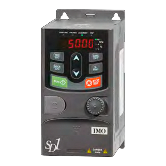
Page 32: Chapter 4 Keypad Operation
SD1 Series Inverters Keypad Operation Chapter 4 Keypad Operation 4.1 Keypad Introduction You can use the keypad to control the start and stop, read status data, and set parameters of the inverter. RUN/TUNE FWD/REV LOCAL/REMOT TRIP DATA QUICK SHIFT STOP... - Page 33 SD1 Series Inverters Keypad Operation Name Description LED blinking the inverter is in parameter autotune LED on the inverter is running LED off the inverter will run in the forward direction. FWD/REV LED on the inverter will run in the reverse direction...
- Page 34 SD1 Series Inverters Keypad Operation Name Description Programm Enter or escape from the first level menu and ing key remove the parameter quickly Enter the menu step-by-step DATA Entry key Confirm parameters UP key Increase data or function code progressively...
-
Page 35: Keypad Display
SD1 Series Inverters Keypad Operation 4.2 Keypad Display The keypad of SD1 series inverter displays the stopped-state parameters, running-state parameters, function parameter editing status, and fault alarm status. 4.2.1 Stop mode parameter When the inverter is in stopped state, the keypad displays stopped-state parameters. -
Page 36: Operations On The Keypad
SD1 Series Inverters Keypad Operation display interface. On the function parameter display interface, you can press the DATA/ENT key to save parameter settings or press the PRG/ESC key to exit the parameter display interface. RUN/TUNE FWD/REV LOCAL/REMOT TRIP RUN/TUNE FWD/REV LOCAL/REMOT TRIP... -
Page 37: Setting A Password For The Inverter
Figure 4-4 Modifying a parameter 4.3.2 Setting a password for the inverter SD1 series inverters provide password protection function to users. Set P07.00 to gain the password and the password protection becomes effective 1 minute later after retreating from the function code editing state. Press PRG/ESC again to the function code editing state, "0.0.0.0.0"... -
Page 38: Chapter 5 Function Parameters
Function Parameters Chapter 5 Function Parameters The function parameters of SD1 series inverters have been divided into 30 groups (P00~P29) according to the function, of which P18~P28 are reserved. Each function group contains certain function codes. A three-level menu style is applied to function codes. For example, "P08.08"... - Page 39 SD1 Series Inverters Function Parameters Function Name Description Default Modify code 2: SVPWM control Suitable in applications which do not need high control accuracy, such as the load of fan and pump. One inverter can drive multiple motors. Note: Motor parameter autotuning is required when vector mode is applied.
- Page 40 SD1 Series Inverters Function Parameters Function Name Description Default Modify code The lower limit of the running frequency is that of the output frequency of the inverter. The inverter runs at the lower limit frequency if Lower limit of the set frequency is lower than the lower limit.
- Page 41 SD1 Series Inverters Function Parameters Function Name Description Default Modify code corresponds to the maximum frequency in forward direction (function code P00.03) and -100.0% corresponds to the maximum frequency in reverse direction (function code P00.03). Note: The pulse setting can only be input by multi-function terminals HDI.
- Page 42 Depend frequency (P00.03) to 0Hz. Deceleration ○ P00.12 SD1 series inverters have four groups of time 1 model ACC/DEC time which can be selected by P05. The default ACC/DEC time of the inverter is the -37-...
- Page 43 SD1 Series Inverters Function Parameters Function Name Description Default Modify code first group. Setting range P00.11 P00.12: 0.0~3600.0s 0: Runs at the default direction, the inverter runs in the forward direction. FWD/REV indicator is off. 1: Runs at the opposite direction, the inverter runs in the reverse direction.
- Page 44 SD1 Series Inverters Function Parameters Function Name Description Default Modify code current waveform, little current harmonic wave, and motor noise. The disadvantage of high carrier frequency: increasing the switch loss, increasing inverter temperature and the impact to the output capacity. The inverter needs to derate on high carrier frequency.
-
Page 45: P01 Group Start And Stop Control
SD1 Series Inverters Function Parameters Function Name Description Default Modify code restore 0: No operation parameter 1: Restore the default value (excluding the motor parameters) 2: Clear fault records 3: Function code locking (lock all function codes) 4: Reserved 5: Restore the default value (factory test mode) - Page 46 SD1 Series Inverters Function Parameters Function Name Description Default Modify code Starting frequency of direct start-up means the Starting original frequency during the inverter starting. ◎ P01.01 frequency of 0.50Hz See P01.02 for detailed information. direct start-up Setting range: 0.00~50.00Hz Set a proper starting frequency to increase the torque of the inverter during starting.
- Page 47 SD1 Series Inverters Function Parameters Function Name Description Default Modify code The changing mode of the frequency during start-up and running. 0: Linear type The output frequency increases or decreases linearly. Output frequency fmax Acceleration/ 1: S curve ◎ P01.05...
- Page 48 SD1 Series Inverters Function Parameters Function Name Description Default Modify code immediately. And the load coasts to stop at the mechanical inertia. Starting Starting frequency of DC braking: start the DC frequency of braking when running frequency reaches starting ○...
- Page 49 SD1 Series Inverters Function Parameters Function Name Description Default Modify code Output frequency Shift after the starting frequency Starting Shift after the zero frequency frequency Setting range: 0.0~3600.0s Set the threshold point of the inverter: 0: Switch at zero frequency FWD/REV ◎...
- Page 50 SD1 Series Inverters Function Parameters Function Name Description Default Modify code Inverter won't run, and the system keeps in the protection state until the running command is canceled and enabled again. 1: The terminal running command is valid when powering on. If the running command is detected...
-
Page 51: P02 Group Motor 1 Parameters
SD1 Series Inverters Function Parameters Function Name Description Default Modify code 1: Enabled, if the starting need is met, the inverter will run automatically after waiting for the time defined by P01.22. The function determines the waiting time before the automatic running of the inverter when powering off and powering on. - Page 52 SD1 Series Inverters Function Parameters Function Name Description Default Modify code Depend Rated voltage ◎ P02.04 0~1200V of async-motor model Depend Rated current ◎ P02.05 0.8~6000.0A of async-motor model Depend Stator resistor ○ P02.06 0.001~65.535Ω of async-motor model Depend Rotor resistor ○...
- Page 53 SD1 Series Inverters Function Parameters Function Name Description Default Modify code coefficient 4 for the iron core of async-motor 1 0: No protection 1: Common motor (with low-speed compensation). Because the heat-releasing effect of the common motors will be weakened, the corresponding electric heat protection will be adjusted properly.
-
Page 54: P03 Group Vector Control
SD1 Series Inverters Function Parameters Function Name Description Default Modify code Time t (min) Times of motor overload 200% 116% 150% 180% Setting range: 20.0%~120.0% Correct the power displaying of motor 1. Correction Only impact the displaying value other than the ○... - Page 55 SD1 Series Inverters Function Parameters Function Name Description Default Modify code Setting range of P03.02: 0.00Hz~P00.05 Setting range of P03.05: P03.02~P00.03 Speed loop ○ P03.06 0~8 (corresponds to 0~2 /10ms) output filter Compensation coefficient of Slip compensation coefficient is used to adjust ○...
- Page 56 SD1 Series Inverters Function Parameters Function Name Description Default Modify code Keypad setting Setting range: -300.0%~300.0% (motor rated ○ P03.12 50.0% torque current) Torque ○ P03.13 reference filter 0.000~10.000s 0.100s time Setting source 0: Set via keypad (P03.16 sets P03.14, P03.17 of upper-limit sets P03.15)
- Page 57 SD1 Series Inverters Function Parameters Function Name Description Default Modify code braking torque motor current) 2: Set via AI2 (same as above) 3: Set via AI3 (same as above) 4: Set via HDI (same as above) 5: Set via Modbus communication (same as...
-
Page 58: P04 Group Svpwm Control
SD1 Series Inverters Function Parameters Function Name Description Default Modify code time up. Build up a magnetic field inside the motor to improve the torque performance during the starting process. The setting time: 0.000~10.000s Flux weakening ○ P03.26 0~8000 1200... - Page 59 SD1 Series Inverters Function Parameters Function Name Description Default Modify code channel set by P00.06 or the voltage reference channel set by P04.27 to change the feature of the curve. Note: V in the below picture is the motor rated voltage and f is the motor rated frequency.
- Page 60 SD1 Series Inverters Function Parameters Function Name Description Default Modify code 0.1%~10.0% Setting range of P04.02: 0.0%~50.0% V/F frequency ○ P04.03 0.00Hz Output voltage point 1 100.0% V/F voltage ○ P04.04 0.0% point 1 V/F frequency ○ P04.05 0.00Hz Output...
- Page 61 SD1 Series Inverters Function Parameters Function Name Description Default Modify code control factor especially the motor with big power. The motor cannot run stably, or overcurrent may occur. High frequency These phenomena can be canceled by adjusting P04.11 vibration ○...
-
Page 62: P05 Group Input Terminals
SD1 Series Inverters Function Parameters Function Name Description Default Modify code Output Set the upper and low limit of the output voltage. ◎ P04.31 maximum Setting range of P04.31: P04.32~100.0% 100.0% voltage (The rated voltage of the motor) Setting range of P04.32: 0.0%~P04.31... - Page 63 SD1 Series Inverters Function Parameters Function Name Description Default Modify code 7: Fault reset S4 terminal 8: Operation pause ◎ P05.04 function 9: External fault input selection 10: Increasing frequency setting (UP) S5 terminal 11: Decreasing frequency setting (DOWN) ◎...
- Page 64 SD1 Series Inverters Function Parameters Function Name Description Default Modify code 40: Clear the power consumption 41: Keep the power consumption 42: Emergency stop 43~60: Reserved 61: PID pole switching 62~63: Reserved When the terminal acts as ACC/DEC time selection, you need to select four groups of ACC/DEC time through state combinations of these two terminals.
- Page 65 SD1 Series Inverters Function Parameters Function Name Description Default Modify code BIT5: S6 virtual terminal BIT6: S7 virtual terminal BIT7: S8 virtual terminal BIT8: HDI virtual terminal Note: After a virtual terminal is enabled, the state of the terminal can only be modified through communication, and the communication address is 0x200A.
- Page 66 SD1 Series Inverters Function Parameters Function Name Description Default Modify code The direction control is as follows during operation: Previous Current direction direction Forward Reverse OFF→ON Reverse Forward Reverse Forward ON→OFF Forward Reverse ON→ Decelerate to stop 3: 3-wire control 2; Sin is the enabling terminal in...
- Page 67 SD1 Series Inverters Function Parameters Function Name Description Default Modify code FWD/REV terminal is valid, the inverter stops because of the stopping command from other sources, even the control terminal FWD/REV keeps valid; the inverter won't work when the stopping command is canceled. Only when FWD/REV is re-launched, the inverter can start again.
- Page 68 SD1 Series Inverters Function Parameters Function Name Description Default Modify code switching off delay time Lower limit of AI1 is set by the analog potentiometer, AI2 is set ○ P05.32 0.00V by control terminal AI2 and AI3 is set by control Corresponding terminal AI3.
- Page 69 SD1 Series Inverters Function Parameters Function Name Description Default Modify code Corresponding Setting range of P05.34: P05.32~10.00V ○ P05.45 middle setting Setting range of P05.35: -100.0%~100.0% 0.0% of AI3 Setting range of P05.36: 0.000s~10.000s Setting range of P05.37: 0.00V~P05.39 Upper limit of ○...
-
Page 70: P06 Group Output Terminals
SD1 Series Inverters Function Parameters P06 Group Output Terminals Function Name Description Default Modify code 0: Invalid Y1 output ○ P06.01 1: In operation selection 2: Forward rotation operation Relay RO1 3: Reverse rotation operation ○ P06.03 output 4: Jogging operation... - Page 71 SD1 Series Inverters Function Parameters Function Name Description Default Modify code BIT3 BIT2 BIT1 BIT0 Reserved Setting range: 0~F Y1 open delay ○ P06.06 Setting range: 0.000~50.000s 0.000s time Y1C off delay ○ P06.07 Setting range: 0.000~50.000s 0.000s time RO1 switching The function code defines the corresponding ○...
- Page 72 SD1 Series Inverters Function Parameters Function Name Description Default Modify code 15: Value 2 set through Modbus communication 16: Value 1 set through PROFIBUS/CANopen/ DeviceNet communication 17: Value 2 set through PROFIBUS/CANopen/ DeviceNet communication 18: Value 1 set through Ethernet communication...
-
Page 73: P07 Group Hmi
SD1 Series Inverters Function Parameters Function Name Description Default Modify code Corresponding 10V (20mA) ○ 0.00V P06.23 AO2 output to the lower limit Upper limit of ○ 100.0% P06.24 AO2 output 0.0% 100.0% Corresponding Setting range of P06.17: -100.0%~ P06.19 ○... - Page 74 SD1 Series Inverters Function Parameters Function Name Description Default Modify code 0: No operation 1: Upload the local function parameter to the keypad 2: Download the keypad function parameter to local address (including the motor parameters) 3: Download the keypad function parameter to...
- Page 75 SD1 Series Inverters Function Parameters Function Name Description Default Modify code Select stop function STOP/RST. STOP/RST is effective in any state for the keypad reset. STOP/RST 0: Only valid for the keypad control ○ P07.04 stop function 1: Both valid for keypad and terminals control...
- Page 76 SD1 Series Inverters Function Parameters Function Name Description Default Modify code 0x0000~0xFFFF BIT0: Set frequency (Hz on, frequency flickering slowly) BIT1: Bus voltage (V on) BIT2: Input terminals state BIT3: Output terminals state BIT4: PID reference (% flickering) The parameter BIT5: PID feedback value (% flickering) ○...
- Page 77 SD1 Series Inverters Function Parameters Function Name Description Default Modify code High bit of Display the power used by the inverter. ● P07.15 power power consumption inverter consumption =P07.15×1000+P07.16 Low bit of Setting range of P07.15: 0~65535kWh (*1000) ● P07.16 power Setting range of P07.16: 0.0~999.9kWh...
- Page 78 SD1 Series Inverters Function Parameters Function Name Description Default Modify code 15: Overheat of rectifier module (OH1) 16: Overheat fault of inverter module (OH2) 17: External fault (EF) 18: 485 communication faults (CE) 19: Current detection fault (ItE) 20: Motor autotune fault (tE)
-
Page 79: P08 Group Enhanced Functions
SD1 Series Inverters Function Parameters Function Name Description Default Modify code ● P07.45 Bus voltage of the last fault 0.0V ● P07.46 Max. temperature of the last fault 0.0°C ● P07.47 Input terminals state of the last fault ● P07.48 Output terminals state of the last fault ●... - Page 80 SD1 Series Inverters Function Parameters Function Name Description Default Modify code Setting range: 0.00Hz~P00.03 (the max. frequency) Jogging The jogging acceleration time means the time running ○ P08.07 needed if the inverter runs from 0Hz to the max. acceleration frequency.
- Page 81 SD1 Series Inverters Function Parameters Function Name Description Default Modify code declining time Output frequency Jumping frequency Wobble frequency amplitude Center frequency Decelerate per dec. time Lower limit of wobble frequency Accelerate Fall time of Rise time of wobble frequency...
- Page 82 SD1 Series Inverters Function Parameters Function Name Description Default Modify code emergency stop 0.0~3600.0s Delay to enter It indicates the delay to enter the sleep state, and ○ 2.0s P08.22 the sleep state it is valid only when ones place of P01.19 is set to 2.
- Page 83 SD1 Series Inverters Function Parameters Function Name Description Default Modify code output the signal of "running time arrival". Setting range: 0~65535min Time of fault The time of the fault reset: set the fault reset time ○ P08.28 reset by selecting this function. If the reset time exceeds this set value, the inverter will stop for the fault and wait to be repaired.
- Page 84 SD1 Series Inverters Function Parameters Function Name Description Default Modify code (The max. frequency) When the output frequency is among the below or above range of the set frequency, the multi-function digital output terminal will output the signal of "frequency arrival", see the diagram...
- Page 85 SD1 Series Inverters Function Parameters Function Name Description Default Modify code no less than 10% of the inverter rated current. If the inverter ramp frequency is 0 Hz and the inverter output current is less than 10% of the inverter rated current or the inverter stops running, the fan stops running within 1 minute.
- Page 86 SD1 Series Inverters Function Parameters Function Name Description Default Modify code adjustments are valid Tens place: frequency control selection 0: Valid only when P00.06=0 or P00.07=0 1: Valid for all frequency setting modes 2: Invalid for Preset speed when Preset speed...
- Page 87 SD1 Series Inverters Function Parameters Function Name Description Default Modify code DOWN terminal frequency ○ P08.46 0.01~50.00s 0.50 s decrement integral speed ratio 0x000~0x111 Ones place: Action of the digital regulation frequency at power off. 0: Save when power off...
-
Page 88: P09 Group Pid Control
SD1 Series Inverters Function Parameters Function Name Description Default Modify code So, the magnetic flux can be used in the motor stop, as well as to change the rotation speed of the motor. Its other advantages are: Brake immediately after the stop command. It does not need to wait until the magnetic flux weakens. - Page 89 SD1 Series Inverters Function Parameters Function Name Description Default Modify code The function code is mandatory when P09.00=0. PID value The basic value of the function code is the ○ P09.01 0.0% reference feedback of the system. Setting range: -100.0%~100.0% Select the PID channel by the parameter.
- Page 90 SD1 Series Inverters Function Parameters Function Name Description Default Modify code reference is 100%, the integral adjustor works continuously after time (ignoring proportional effect and differential effect) to achieve the max. frequency (P00.03) or the max. voltage (P04.31). Shorter the integral time, stronger is the adjustment Setting range: 0.00~10.00s...
- Page 91 SD1 Series Inverters Function Parameters Function Name Description Default Modify code Feedback value Bias limit Reference value Output frequency Setting range: 0.0~100.0% Upper limit of These parameters are used to set the upper and ○ P09.09 100.0% PID output lower limit of the PID adjustor output.
- Page 92 SD1 Series Inverters Function Parameters Function Name Description Default Modify code the reference and the feedback changes, it needs more time to offset the impact of continuous working and the integration will change with the trend. 1: Stop integral adjustment when the frequency reaches the upper/lower limit.
-
Page 93: P10 Group Simple Plc And Preset Speed Control
SD1 Series Inverters Function Parameters Function Name Description Default Modify code 0.00Hz~P09.21 When the ramp frequency is no greater than Low point P09.20, current parameters frequency of P09.17~P09.19. When the ramp frequency is no P09.20 ○ 5.00Hz PID parameter less than P09.21, current PID parameters are switching P09.04~P09.06. - Page 94 3 Preset speeds are in the range of --f ○ 0.0% P10.10 Preset speed 4 it can be set continuously. SD1 series inverters can set 16 stages speed, Running time ○ 0.0s P10.11 selected by the combination of Preset terminals of step 4 1~4, corresponding to the speed 0 to speed 15.
- Page 95 SD1 Series Inverters Function Parameters Function Name Description Default Modify code step Terminal 1 OFF ON ON OFF ON OFF ON Running time ○ 0.0s P10.27 of step 12 Terminal 2 OFF OFF ON OFF OFF ON ON Preset speed ○...
-
Page 96: P11 Group Protection Parameters
SD1 Series Inverters Function Parameters Function Name Description Default Modify code change into decimal bit, and then set the corresponding function codes. Setting range: -0x0000~0xFFFF 0: Restart from the first stage; stop during running (caused by the stop command, fault, or power loss), run from the first stage after restart. - Page 97 SD1 Series Inverters Function Parameters Function Name Description Default Modify code frequency at P11.02, to make the inverter generate power again. The returning power can maintain the bus voltage to ensure a rated running of the inverter until the recovery of power.
- Page 98 SD1 Series Inverters Function Parameters Function Name Description Default Modify code during current level, the inverter will run at stable frequency in limit accelerated running, or the inverter will derate to run during the constant running. If it exceeds the level continuously, the output frequency will keep on decreasing to the lower limit.
- Page 99 SD1 Series Inverters Function Parameters Function Name Description Default Modify code Setting range: 0x000~0x132 Ones place: 0: Motor overload/underload pre-alarm, relative to rated motor current. 1: inverter overload/underload pre-alarm, relative to rated inverter current. 2: Motor output torque overload/underload pre-alarm, relative to rated motor torque...
-
Page 100: P13 Group Sm Control
SD1 Series Inverters Function Parameters Function Name Description Default Modify code 0: Action during the automatic reset period 1: No action during the automatic reset period 0x000~0x111 Ones place: Automatic frequency-drop at voltage drop 0: Disable 1: Enable Tens place:... -
Page 101: P14 Group Serial Communication
SD1 Series Inverters Function Parameters Function Name Description Default Modify code the percentage of rated current of the inverters) Setting range of P13.14: 0.00~50.00s P14 Group Serial Communication Function Name Description Default Modify code Setting range: 1~247 When the master is writing the frame, the communication address of the slave is set to 0;... - Page 102 SD1 Series Inverters Function Parameters Function Name Description Default Modify code 6: No check (N, 7, 1) for ASCII 7: Even check (E, 7, 1) for ASCII 8: Odd check (O, 7, 1) for ASCII 9: No check (N, 7, 2) for ASCII...
-
Page 103: P17 Group Status Viewing
SD1 Series Inverters Function Parameters Function Name Description Default Modify code action selection 0: Yes 1: No Tens place: Communication encryption 0: Disabled 1: Enabled Hundreds place: User-defined communication command address 0: Disabled 1: Enabled User-defined address for ○ 0x0000~0xffff P14.07... - Page 104 SD1 Series Inverters Function Parameters Function Name Description Default Modify code Display the power of the motor. ● P17.08 Motor power Setting range: -300.0%~300.0% (the rated current of the motor) Display the output torque of the inverter. ● P17.09 Output torque Range: -250.0~250.0%...
- Page 105 SD1 Series Inverters Function Parameters Function Name Description Default Modify code PID feedback Display PID feedback value ● P17.24 value Range: -100.0~100.0% Power factor of Display the power factor of the motor. ● P17.25 the motor Range: -1.00~1.00 Current Display the current running time of the inverter.
- Page 106 SD1 Series Inverters Function Parameters Function Name Description Default Modify code Process PID ● P17.42 0.00~10.00s differential time -101-...
-
Page 107: Chapter 6 Fault Tracking
6.1.1 Periodical maintenance If the inverter is installed in an environment that meets requirements, little maintenance is needed. The following table describes the routine maintenance periods recommended by IMO. For more detailed information on maintenance, please contact us. Item to be checked... - Page 108 SD1 Series Inverters Fault Tracking Item to be checked Details Check mode Criterion mean that there is something wrong with features. Ensure that there is no distortion or color-changing of the Visual examination NA conductors caused by Conductor lead overheating.
-
Page 109: Cooling Fan
SD1 Series Inverters Fault Tracking Item to be checked Details Check mode Criterion Ensure the contactor is Visual examination NA good enough. Ensure there are no loose screws and Fasten up contactors. Ensure there is no Smelling and visual odors and color examination changing. -
Page 110: Capacitor
Fault Tracking operated in a critical part of a process, fan replacement is recommended once these symptoms appear. Replacement fans are available from IMO. Read and follow the instructions in Chapter 1 "Safety Precautions". Ignoring the instructions would cause physical injury or death, or damage to the equipment. -
Page 111: Power Cable
The electrolytic capacitor of the inverter must be replaced if it has been used for more than 35,000 hours. For details about the replacement, contact the local IMO office or dial our national service hotline (400-700-9997). 6.1.4 Power cable ... -
Page 112: Fault Solution
Using the information given in this chapter, most alarm and fault causes can be identified and corrected. If not, contact the IMO office. 6.2.2 Fault reset The inverter can be reset by pressing the keypad key STOP/RST, through digital input, or by switching the power light. - Page 113 SD1 Series Inverters Fault Tracking Fault Fault type Possible cause Solutions code Over-current Increase acceleration time. during Check input power. Acceleration is too fast. acceleration Select the inverter with a Grid voltage is too low.
- Page 114 SD1 Series Inverters Fault Tracking Fault Fault type Possible cause Solutions code Acceleration is too fast. Increase acceleration time. Restart the rotating motor Avoid restarting after Grid voltage is too low. stopping. Inverter ...
- Page 115 SD1 Series Inverters Fault Tracking Fault Fault type Possible cause Solutions code The connection of the Check the connector and control board is not good. plug wire again. Current Assistant power is bad. Change the board.
- Page 116 SD1 Series Inverters Fault Tracking Fault Fault type Possible cause Solutions code The keypad is not in good Check the keypad cable connection or offline. and ensure it is normal. The keypad cable is too Keypad...
- Page 117 SD1 Series Inverters Fault Tracking Fault Fault type Possible cause Solutions code The inverter will report the Electronic Check the load and the underload pre-alarm underload fault underload pre-alarm point. according to the set value. STO function operates...
- Page 118 SD1 Series Inverters Fault Tracking disappear automatically after state restoration, which requires no reset action. After reset of external running command, the drive will execute running command again. Running command Stop Running Running Running VFD output Stop Running Fig 6.4 STL1 fault As shown in below fig 6.5, when the hardware circuit of safety circuit 1 is abnormal while that...
-
Page 119: Other States
SD1 Series Inverters Fault Tracking Running command Stop Running Running Running VFD output Stop Reset Reset (RST) Fig 6.6 6.2.4 Other states Fault code Fault type Possible cause Solutions System power off or low DC PoFF System power off Check the grid... -
Page 120: Chapter 7 Communication Protocol
SD1 Series Inverters Communication Protocol Chapter 7 Communication Protocol 7.1 Modbus Protocol Introduction Modbus protocol is a software protocol and common language which is applied in the electrical controller. With this protocol, the controller can communicate with other devices via a network (the channel of signal transmission or the physical layer, such as RS485). - Page 121 SD1 Series Inverters Communication Protocol -2V~-6V; it is logic "0". 485+ on the terminal board corresponds to A and 485- to B. Communication baud rate means the binary bit number in one second. The unit is bit/s (bps). The higher the baud rate is, the quicker the transmission speed is and the weaker the anti-interference is.
- Page 122 SD1 Series Inverters Communication Protocol Twisted pairs with shied screen RS485 Rout Earth Earth 485- 485+ Convert from RS232 to RS485 Computer Figure 7-1 RS485 wiring diagram for the network with one inverter 7.2.1.2 When multiple inverters are used In real multi-applications, the chrysanthemum connection and star connection are commonly used.
-
Page 123: Rtu Mode
SD1 Series Inverters Communication Protocol 7.2.2 RTU mode 7.2.2.1 RTU communication frame structure If the controller is set to communicate by RTU mode in Modbus network every 8bit byte in the message includes two 4Bit hex characters. Compared with ACSII mode, this mode can send more data at the same baud rate. - Page 124 SD1 Series Inverters Communication Protocol The standard structure of RTU frame: START T1-T2-T3-T4 (transmission time of 3.5 bytes) Communication address: 0~247 (decimal system) (0 is the ADDR broadcast address) 03H: read slave parameters 06H: write slave parameters DATA (N-1) The data of 2*N bytes are the main content of the communication …...
- Page 125 SD1 Series Inverters Communication Protocol is applied, the even check bit is "1"; if the odd checkout is applied; the odd check bit is "0". The even and odd check bit is calculated on the check bit position of the frame. And the receiving devices also carry out even and odd checkout.
-
Page 126: Ascii Mode
SD1 Series Inverters Communication Protocol 7.2.3 Ascii mode Name Definition Communication protocol belongs to hexadecimal system. The meaning of message character in ASCII: "0"…"9", "A"…"F", each hex is represented by the ASCII message corresponds to the character. Coding Character system... -
Page 127: Command Code And Communication Data
SD1 Series Inverters Communication Protocol LRC CHK Hi LRC check code: 8-bit check code is formed by the combination of two ASCII LRC CHK Lo codes. END Hi End character: END Hi=CR (0x0D), END Lo=LF (0x0A) END Lo 7.2.3.1 ASCII mode check (LRC Check) Check code (LRC Check) is the value combined of address and data content result. - Page 128 SD1 Series Inverters Communication Protocol ADDR High bit of the start address Low bit of the start address High bit of data number Low bit of data number CRC low bit CRC high bit T1-T2-T3-T4 T1-T2-T3-T4 between START and END is to provide at least the time of 3.5 bytes as the leisure time and distinguish two messages for the avoidance of taking two messages as one message.
- Page 129 SD1 Series Inverters Communication Protocol and ADDR occupies one byte CMD=03H means the message is received from the inverter to the master for the response of reading command and CMD occupies one byte "Byte number" means all byte number from the byte (excluding the byte) to CRC byte (excluding the byte).
- Page 130 SD1 Series Inverters Communication Protocol Low bit of data content CRC CHK low bit CRC CHK high bit T1-T2-T3-T4 Note: Sections 7.2 and 7.3 mainly describe the command formats. 7.3.1.3 Command code 08H, diagnosis Meaning of sub-function codes Sub-function Code...
-
Page 131: Ascii Mode
SD1 Series Inverters Communication Protocol For example, write 5000 (1388H) to 0004H of the inverter whose slave address is 02H and 50 (0032H) to 0005H, the frame structure is as follows: The RTU request command is: START T1-T2-T3-T4 (transmission time of 3.5 bytes) - Page 132 SD1 Series Inverters Communication Protocol ASCII master command message (the ASCII slave response message (the command sent from the master to the message sent from the inverter to the inverter master) START START ADDR ADDR High bit of starting address...
- Page 133 SD1 Series Inverters Communication Protocol ASCII master command message (the ASCII slave response message (the command sent by the master to inverter) message sent by the inverter to master) Low bit of data content Low bit of data content LRC CHK Hi...
-
Page 134: Data Address Definition
SD1 Series Inverters Communication Protocol For instance: Write 5000 (1388H) to 0004H of the inverter whose slave address is 02H, write 50 (0032H) to 0005H of the inverter whose slave address is 02H, then the structure of this frame is listed as below:... -
Page 135: Description Of Other Function Addresses In Modbus
SD1 Series Inverters Communication Protocol MSB—00~ffH; LSB—00~ffH. The MSB is the group number before the radix point of the function code and the LSB is the number after the radix point, but both the MSB and the LSB should be converted into hex. For example, P05.05, the group number before the radix point... - Page 136 SD1 Series Inverters Communication Protocol Address Function instruction Data meaning instruction definition attribute 0007H: Fault reset 0008H: Jogging stop Communication setting frequency 2001H (0~Fmax (unit: 0.01Hz)) PID reference, range (0~1000, 1000 2002H corresponds to100.0%) PID feedback, range (0~1000, 1000 2003H corresponds to100.0%)
- Page 137 SD1 Series Inverters Communication Protocol Address Function instruction Data meaning instruction definition attribute (0~1000, 1000 corresponds 100.0% of the rated voltage of the motor) AO output setting 1 200DH (-1000~1000, 1000 corresponds 100.0%) AO output setting 2 200EH (-1000~1000, 1000 corresponds 100.0%)
- Page 138 SD1 Series Inverters Communication Protocol Address Function instruction Data meaning instruction definition attribute 0.1% -250.0~250.0%, unit: Output torque 3007H 0.1% -100.0~100.0%, unit: PID setting 3008H 0.1% -100.0~100.0%, unit: PID feedback 3009H 0.1% Input state 300AH 000~1FF Input state 300BH 000~1FF 0.00~10.00V, unit:...
-
Page 139: Fieldbus Scale
SD1 Series Inverters Communication Protocol The encoding rules for device codes (corresponds to identifying code 2103H of the inverter) MSB of code Meaning LSB of code Meaning SD1 Series Vector SD1 Vector inverter Inverter Note: The code is consisted of 16 bit which is high 8 bits and low 8 bits. High 8 bits mean the motor type series and low 8 bits mean the derived motor types of the series. -
Page 140: Error Message Response
SD1 Series Inverters Communication Protocol Read Parameters 2-byte CRC check address command data data Because the parameter data is 0032H (50) and 50 divided by 10 is 5, then the hibernation restore delay time is 5s. 7.4.4 Error message response Operation errors may occur in communication-based control. - Page 141 SD1 Series Inverters Communication Protocol Code Name Meaning cannot be upper computer cannot be modified during the running of the modified in inverter. running A user password is set, and the upper computer does not Password provide the password to unlock the system when performing protection a read or write operation.
-
Page 142: Read/Write Operation Example
SD1 Series Inverters Communication Protocol 7.5 Read/Write Operation Example Refer to section 7.3 for the command format. 7.5.1 Example of reading command 03h Example 1: Read the state word 1 of the inverter with the address of 01H (refer to the parameter table of other functions). - Page 143 SD1 Series Inverters Communication Protocol Function Address Data meaning instruction instruction definition characteristics 0003H: Forward jogging 0004H: Reverse jogging 0005H: Stop 0006H: Coast to stop (emergency stop) 0007H: Fault reset 0008H: Jogging stop RTU mode: The command sent by the master:...
-
Page 144: Examples Of Continuously Writing Command 10H
SD1 Series Inverters Communication Protocol Write Parameters Parameter data CRC check address command address If the operation is successful, the response may be as below (the same with the command sent by the master): Write Parameters Parameter data CRC check... - Page 145 SD1 Series Inverters Communication Protocol Function Address Data meaning instruction instruction definition attribute corresponds to100.0%) RTU mode: The command sent to the inverter: Continuous Parameters Data Byte Forward 10Hz CRC check writing address address number number running command If the operation succeeds, the response message is as follows:...
-
Page 146: Common Communication Faults
SD1 Series Inverters Communication Protocol Continuous Parameters Data CRC check address writing address number command ASCII mode: The command sent to the inverter: Continuous Parameters Data writing address check address number command If the operation succeeds, the response message is as follows:... -
Page 147: Appendix A Technical Data
When the altitude of the site where the inverter is installed is lower than 1000m, the inverter can run at the rated power. When the altitude exceeds 1000m, derate by 1% for every increase of 100m. When the altitude exceeds 3000m, consult the local IMO dealer or office for details. -
Page 148: Ce Marking
SD1 Series Inverters Technical Data A.2 CE A.2.1 CE marking The CE mark is attached to the drive to verify that the drive follows the provisions of the European Low Voltage (2014/35/EU) and EMC Directives (2014/30/EU). A.2.2 Compliance with the European EMC directive The EMC Directive defines the requirements for immunity and emissions of electrical equipment used within the European Union. -
Page 149: Inverters Of Category C3
SD1 Series Inverters Technical Data In a domestic environment, this product may cause radio inference, in which case supplementary mitigation measures may be required. A.3.2 Inverters of category C3 The anti-interference performance of the inverter meets the requirements of environments Category II in the IEC/EN 61800-3 standard. -
Page 150: Appendix B Dimension Drawings
SD1 Series Inverters Dimension Drawings Appendix B Dimension Drawings Dimension drawings of the SD1 are shown as follows. The dimensions are given in mm. B.1 External Keypad Structure Figure B-1 Keypad dimensions 42.0 17.1 19.0 48.1 19.0 62.0 2-Ø4.5 16.0 26.0... -
Page 151: Inverter Chart
SD1 Series Inverters Dimension Drawings Installation bracket 1 Customer installation dimensions Installation bracket 2 Customer installation dimensions Figure B-3 Outline and installation dimensions B.2 Inverter Chart Figure B-4 Wall mounting of 0.75~2.2kW inverters (Dimension unit: mm) Mounting Weight Model hole... - Page 152 SD1 Series Inverters Dimension Drawings Mounting Weight Model hole (kg) diameter (d) SD1-2.5A-21 80.0 60.0 160.0 150.0 123.5 120.3 Ø 5 SD1-4.2A-21 80.0 60.0 160.0 150.0 123.5 120.3 Ø 5 SD1-7.5A-21 80.0 60.0 185.0 175.0 140.5 137.3 Ø 5 SD1-10A-21 80.0...
- Page 153 SD1 Series Inverters Dimension Drawings Figure B-6 Wall mounting of 3PH 400V 4~37kW and 3PH 230V 1.5~7.5kW inverters Figure B-7 Wall mounting of 3PH 400V 45~75kW inverters Figure B-8 Wall mounting of 3PH 400V 90~110kW inverters (Dimension (unit: mm)) -148-...
- Page 154 SD1 Series Inverters Dimension Drawings Mounting hole Weight Model diameter (kg) SD1-7.5A-23 146.0 131.0 — 256.0 243.5 167.0 84.5 Ø 6 SD1-10A-23 146.0 131.0 — 256.0 243.5 167.0 84.5 Ø 6 SD1-16A-23 146.0 131.0 — 256.0 243.5 167.0 84.5 Ø 6 SD1-20A-23 170.0 151.0...
- Page 155 SD1 Series Inverters Dimension Drawings Figure B-10 Flange mounting of 3PH 400V 90~110kW inverters Dimension (unit: mm) Mounting Weight Model W1 W2 W4 H1 H2 hole Screw (kg) diameter (d) SD1-7.5A-23 170.2 131 150 9.5 292 276 260 84.5 Ø 6 SD1-10A-23 170.2 131 150...
-
Page 156: Appendix C Optional Peripheral Accessories
SD1 Series Inverters Optional Peripheral Accessories Appendix C Optional Peripheral Accessories This chapter describes how to select the options and parts of SD1 series. C.1 Wiring of Peripheral Accessories The following figure shows the external wiring of the inverter. LED external keypad... -
Page 157: Power Supply
SD1 Series Inverters Optional Peripheral Accessories Pictures Name Descriptions Device for electric shock prevention and protection against short-to-ground that may cause current leakage and fire. Select residual-current circuit breakers (RCCBs) that are Breaker applicable to inverters and can restrict high-order harmonics, and of which the rated sensitive current for one inverter is larger than 30 mA. -
Page 158: Control Cables
SD1 Series Inverters Optional Peripheral Accessories C.3.2 control cables All analog control cables and cables used for frequency input must be shielded cables. Relay cables need to be those with metal braided shield layers. Note: Analog signals and digital signals cannot use the same cables, and their cables must be arranged separately. -
Page 159: Breaker And Electromagnetic Contactor
The capacity of the breaker needs to be 1.5 to 2 times the rated current of the inverter. It is recommended to use B type breakers for all the IMO inverters. According to the working principle and structure of breakers, if the manufacturer's regulation is not followed, hot ionized gases may escape from the breaker enclosure when a short-circuit occurs. -
Page 160: Reactors
50 m, an output reactor must be added on the output side of the inverter. If the distance between the inverter and motor is 50 m to 100 m, select the reactor according to the following table. If the distance is longer than 100 m, contact IMO's technical support technicians. - Page 161 SD1 Series Inverters Optional Peripheral Accessories Output reactor Input reactor Model Input reactor Output reactor SD1-2.5A-21 SD1-4.2A-21 SD1-7.5A-21 SD1-10A-21 SD1-2.5A-23 ACLC-1.5-4 OCLC-1.5-4 SD1-4.2A-23 ACLC-1.5-4 OCLC-1.5-4 SD1-7.5A-23 ACLC-4.0-4 OCLC-4.0-4 SD1-10A-23 ACLC-4.0-4 OCLC-4.0-4 SD1-16A-23 ACLC-5.5-4 OCLC-5.5-4 SD1-20A-23 ACLC-7.5-4 OCLC-7.5-4 SD1-30A-23 ACLC-15-4 OCLC-15-4 SD1-2.5A-43-UL...
-
Page 162: Filter
Rated current C.6.2 C3 filter SD1 series 1PH 220V/3PH 380V 2.2kW and below, 3PH 220V 0.75kW and below models can satisfy the requirements of IEC61800-3 C3 as shown in the table below; 3PH 380V 4kW and above, 3PH 220V 1.5kW and above models can be set to satisfy the requirements of IEC61800-3 C3 or not by jumper J10. -
Page 163: Installation Instruction For C3 Filter
SD1 Series Inverters Optional Peripheral Accessories Noise filter on output side: This filter can be used to reduce the radio noise caused between the inverter and motor as well as the leakage current of the lead wires. Model Input filter SD1-2.5A-21... -
Page 164: C2 Filter Model Selection
SD1 Series Inverters Optional Peripheral Accessories C.6.5 C2 filter model selection Model Input filter SD1-2.5A-21 SD1-RFC2-10 SD1-4.2A-21 SD1-7.5A-21 SD1-RFC2-10 SD1-10A-21 SD1-2.5A-23 SD1-RFC2-7 SD1-4.2A-23 SD1-7.5A-23 SD1-RFC2-16 SD1-10A-23 SD1-16A-23 SD1-RFC2-32 SD1-20A-23 SD1-30A-23 SD1-RFC2-45 SD1-2.5A-43 SD1-RFC2-7 SD1-4.2A-43 SD1-5.5A-43 SD1-9.5A-43 SD1-RFC2-16 SD1-14A-43 SD1-18.5A-43 SD1-RFC2-32... -
Page 165: Braking Resistors
Connect the braking resistor or braking unit to the inverter according to the diagram. Incorrect wiring may cause damage to the inverter or other devices. SD1 series inverters have internal braking units. Braking Consumed power of the braking Min. -
Page 166: Braking Resistor Installation
SD1 Series Inverters Optional Peripheral Accessories Braking Consumed power of the braking Min. Type of resistor at resistor (kW) braking Model braking 100% of resistor unit braking (Ω) braking braking braking torque (Ω) SD1-2.5A-43 0.11 0.56 0.90 SD1-4.2A-43 0.23 1.13 1.80... - Page 167 The materials near the braking resistor must be non-flammable. The surface temperature of the resistor is high. Air flowing from the resistor is of hundreds of degrees Celsius. Protect the resistor against contact. SD1 series inverters need only external braking resistors. External brake...
-
Page 168: Appendix D Sto Function Description
Optional Peripheral Accessories SD1 Series Inverters STO Function Description Appendix D STO Function Description Reference standards: IEC 61508-1, IEC 61508-2, IEC 61508-3, IEC 61508-4, IEC 62061, ISO 13849-1, and IEC 61800-5-2. You can enable the safe torque off (STO) function to prevent unexpected startups when the main power supply of the drive is not switched off. -
Page 169: Sto Channel Delay Description
Optional Peripheral Accessories SD1 Series Inverters STO Function Description The STL1, STL2, or STL3 fault occurs. Fault code: Either of H1 and H2 41: Channel H1 exception (STL1) opened, and the 42: Channel H2 exception (STL2) other closed 43: Both channels H1 and H2 are abnormal (STL3) D.2 STO Channel Delay Description... - Page 170 Optional Peripheral Accessories SD1 Series Inverters STO Function Description Item □ Ensure that the drive can be run or stopped randomly during commissioning. Stop the drive (if it is running), disconnect the input power supply, and isolate □ the drive from the power cable through the switch.
-
Page 171: Appendix E Further Information
Appendix E Further Information E.1 Product and Service Inquiries Please address any inquiries about the product to local IMO offices, quoting the model designation and serial number in question. Visit www.imopc.com to obtain IMO sales, support, and service contact information. - Page 172 IMO Precision Controls Ltd The Interchange, Frobisher Way, Hatfield, Herts. UK AL10 9TG Tel: +44 (0)1707 414 444 Email: sales@imopc.com 202205 (v.1.6) Web: www.imopc.com...
Need help?
Do you have a question about the SD1 Series and is the answer not in the manual?
Questions and answers