Table of Contents
Advertisement
Quick Links
Instruction Manual
CANopen option card
HD1-E-COP
Thank you for purchasing your HD1-E-COP option card.
• This product is designed for setting and programming CANopen communication protocol with HD1 series of inverters
• Improper handling might result in incorrect operation, a short life, or even a failure of this product.
• Deliver this manual to the end user of this product. Keep this manual in a safe place until this product is discarded.
• For how to use an optional device, refer to the instruction and installation manuals for that optional device.
IMO Precision Controls Ltd.
HD1-E-COP MANUAL
Advertisement
Table of Contents

Related Manuals for IMO HD1-E-COP


Summary of Contents for IMO HD1-E-COP
- Page 1 CANopen option card HD1-E-COP Thank you for purchasing your HD1-E-COP option card. • This product is designed for setting and programming CANopen communication protocol with HD1 series of inverters • Improper handling might result in incorrect operation, a short life, or even a failure of this product.
- Page 2 All rights reserved. No part of this publication may be reproduced or copied without prior written permission from IMO Precision Controls Ltd. All products and company names mentioned in this manual are trademarks or registered trademarks of their respective holders.
- Page 3 HD1-E CANopen instruction manual Safety precautions Before installing and operating the module, operators must receive professional training on electrics and safety as well as pass the test, and they have been familiar with procedures and requirements about installation, commissioning, running and maintenance of the equipment in avoidance of various emergencies.
- Page 4 HD1-E CANopen instruction manual Terms and abbreviations CAN Controller Area Network COB Communication Object, a transmission unit in CAN network; data are transmitted in the whole network inside COB; one part of CAN information frames EDS Electronic Data System; when configuring CANopen, EDS needs to use the special ASCII file for a node and it contatins the general information on nodes and relevant object dictionary.
-
Page 5: Table Of Contents
HD1-E CANopen instruction manual Content 1. Unpacking inspection ............1 2. General ................1 3. Features ................2 4. Parts introduction ............. 3 5. Wiring ................4 6. Installation ............... 5 7. Communication..............6 7.1 Message structure ............. 6 7.2 State shift ..............7 7.3 NMT ................ -
Page 6: Unpacking Inspection
2. The manual is only for operating guidance and relevant instructions of HD1-E-COP but not for detailed CANopen protocol. Please refer to relevant professional articles or books for more information about CANopen protocol. -
Page 7: Features
HD1-E CANopen instruction manual 3. Features (1) Functions ➢ CAN2.0A protocol ➢ CANopen DS301 (2) Available service ➢ PDO: four pairs of PDO service (PDO1~PDO4 TX, PDO1~PDO4 RX), PDO1 for read and write inverter parameters, PDO2~PDO4 for realtime control and obtaining actual values. ➢... -
Page 8: Parts Introduction
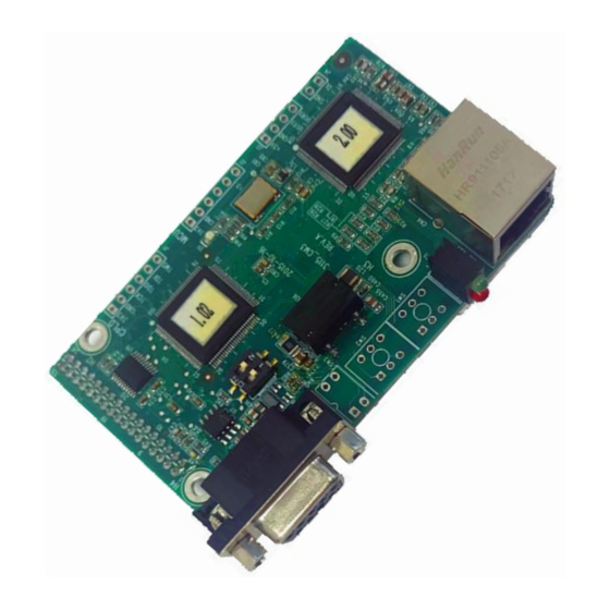
HD1-E CANopen instruction manual 4. Parts introduction See the parts of CANopen communication card in Fig1. Fig1 Parts of CANopen communication card A–CANopen communication port (DB9 female) B–CANopen communication port terminal (3pin) C–CANopen terminating resistor switch D–CANopen status indicator light F–communication card port pin Note: Two address knobs will not be installed, and the communication address is set by inverter function code. -
Page 9: Wiring
Customers are advised to connect the shielded cable to the PE terminal of the inverter when using switch on terminating resistor when the communication card becomes terminating slave station. See the wiring diagram in Fig 2. HD1-E-COP HD1-E-COP HD1-E-COP Fig 2 Wiring diagram... -
Page 10: Installation
HD1-E CANopen instruction manual 6. Installation Procedures for installing HD1-E-COP communication card: 1. Disconnect all power supplies applied to the inverter to ensure safe voltage in the inverter. 2. Remove the cover of the inverter and find the control board. -
Page 11: Communication
HD1-E CANopen instruction manual 7. Communication 7.1 Message structure CAN2.0A message transmits data between the master station and bus nodes via data frame. The message structure is shown as follows: Communication object Function code (binary) COB-ID (hexadecimal) 0x00 SYNC 0x80 EMCY 0x81 ~ 0xFF PDO1 Tx... -
Page 12: State Shift
HD1-E CANopen instruction manual 7.2 State shift HD1-E-COP supports start-up sequence defined by CANopen communication protocol. The following diagram is about NMT state shift of HD1-E-COP. Fig 4 NMT state shift Table7 NMT state shift Trigger action in need State shift... -
Page 13: Nmt
0x80 Enable slave station into pre-operation 0x81 Reset slave station 0x82 Reset node communication ⚫ Example Enable HD1-E-COP of node ID=3 into per-operation. The command is shown as follows: COB-ID Byte0 Byte1 0x000 0x80 0x03 Start all HD1-E-COP nodes in CANopen network. The command is shown as follows:... -
Page 14: Heartbeat Producer
Sometimes, to know the realtime state of the slave station, the master station requires the slave station should automatically send heartbeat producer every interval defined in object dictionary 0x1017 (16bit data length, unit: ms). If time=0, the slave station will not send heartbeat producer. The default heartbeat time of HD1-E-COP is 0. ⚫ Command Slave station→master station... - Page 15 HD1-E CANopen instruction manual Table11 Emergency error code Emergency Description of functions error code (hex) 00xx Error Reset or No Error 10xx Generic Error 20xx Current 21xx Current, device input side 22xx Current, inside the device 23xx Current, device output side 30xx Voltage 31xx...
-
Page 16: Sdo
HD1 inverter manual for inverter unit U-phase protection fault (OUT1). When the fault resets, HD1-E-COP will send following EMCY to inform of the master station that the slave station has no fault. Emergency error code... - Page 17 HD1-E CANopen instruction manual Table15 Terminating error code Termination code Description of code functions 0503 0000 No alternative variation for trigger bit 0504 0000 SDO protocol overtime 0504 0001 Illegal or unknown client or server 0504 0002 Invalid block size 0504 0003 Invalid serial number 0504 0004...
- Page 18 HD1-E CANopen instruction manual ⚫ Example For example, when slave station address is 3, conduct read and write operation on the object of 0x1801 index and 03 sub-index. (Refer to Appendix1 for the object of 0x1801 index and 03 sub-index. The object indicates the prohibition time of PDO2 Tx.) Write example: To modify the prohibition time of PDO2 Tx into 1000ms, write command of the master station goes as follows.
-
Page 19: Pdo
HD1-E CANopen instruction manual 8. PDO The communication card defines four of PDO Tx (0x1800~0x1803) and four of PDO Rx (0x1400~0x1403) for usage. PDO Rx is the PDO command that the slave station receives from the master station while PDO Tx is the PDO command that the slave station sends to the master station. - Page 20 HD1-E CANopen instruction manual Parameter address of HD1 series inverters: The high byte is the number in front of decimal point of the function code while the low byte is the number behind decimal point; the address should be converted into hexadecimal. Take P10.01 for example, 0x0A for the high bit of parameter address due to 10 in front of decimal, 0x01 for the low bit of parameter address due to 01 behind decimal point, so the address of the function code is 0x0A01.
-
Page 21: Pdo2 Rx
HD1-E CANopen instruction manual ⚫ Example For example, when slave station address=3, set the function code of HD1 inverter P15.13=1. Command: The parameter address of P15.02 is 0x0F02. According to the protocol, the request code, parameter address and request data of PDO1 Rx are seperately 0x02, 0x0F0D and 0x01, so PDO1 Rx sent by master station is shown as follows. Request code Parameter address Request data... -
Page 22: Pdo2 Tx
HD1-E CANopen instruction manual ⚫ Example When the slave address=3, adopt CANopen communication to control HD1 inverter and set the running frequency at 50Hz. Command: At first, set start mode of the inverter to CANopen communication (P00.01=2, P00.02=1) and frequency reference way to CANopen communication (P00.06=9). -
Page 23: Pdo3 Rx And Pdo4 Rx
HD1-E CANopen instruction manual ⚫ Example For example, the inverter model is HD1 inverter and the slave address is 3. If the inverter is running, its running frequency equals to 50.00Hz. Set the return value1 to running frequency function, the return value2 to output voltage function and the return value3 to no function. -
Page 24: Sdo
HD1-E CANopen instruction manual 9. SDO Besides PDO, SDO can be also used to monitor the process quantity of the inverter. Users can choose PDO or SDO freely. SDO monitors the inverter by reading object dictionary defined by manufacturer. Please refer to PDO for the definition and usage of the control word, state word, set value and return value in object dictionary defined by manufacturer, and SDO for SDO instruction. - Page 25 HD1-E CANopen instruction manual ⚫ Example Example 1: When the inverter at address 3 runs forward, the master station will send following SDO command. Sub- Request code Object index Request data index COB-ID Byte0 Byte1 Byte2 Byte3 Byte4 Byte5 Byte6 Byte7 0x603 0x2B...
-
Page 26: Baud Rate And Communication Address
HD1-E CANopen instruction manual 10. Baud rate and communication address 10.1 Baud rate setting The setting of CANopen baud rate and communication address is not valid until reboot. CANopen baud rate is set by the function code parameters of the inverter. Please refer to the inverter manual for function code addresses. -
Page 27: State Led
HD1-E CANopen instruction manual 11. State LED Names of CANopen state LED are shown in Table 27. Table 27 Names of CANopen state LED State LED Name Color Running LED (RUN) Green Error LED (ERROR) The descriptions of running LED and error LED are shown in Table 28 and Table 29. Table 28 Description of error LED (ERROR) Error State... -
Page 28: Appendix 1 Od
HD1-E CANopen instruction manual Appendix 1 OD Sub- Index(hex) Description Access right Data type Default value index 1000 Device type Unsigned32 0x0000 0000 1001 Error register Unsigned8 Error code register 1003 Sub-index number Error code Unsigned32 1005 COB-ID SYNC Unsigned32 1006 Communication cycle period Unsigned32... - Page 29 HD1-E CANopen instruction manual Sub- Index(hex) Description Access right Data type Default value index Transmission type Unsigned8 Unsigned16 Unsigned8 Event timer Unsigned16 PDO4 Rx communication parameters Avaliable maximum sub-index Unsigned8 COB-ID used by PDO Unsigned32 1403 Transmission type Unsigned8 Unsigned16 Unsigned8 Event timer Unsigned16...
- Page 30 HD1-E CANopen instruction manual Sub- Index(hex) Description Access right Data type Default value index COB-ID used by PDO Unsigned32 Transmission type Unsigned8 Prohibition time Unsigned16 Reserved Unsigned8 Event timer Unsigned16 PDO4 Tx communication parameters Avaliable maximum sub-index Unsigned8 COB-ID used by PDO Unsigned32 1803 Transmission type...
-
Page 31: Appendix 2 Function Codes (Hd1 Inverter)
HD1-E CANopen instruction manual Appendix 2 Function codes (HD1 inverter) Function Setting Default Name Detailed instruction of parameters Modify code range value 0: Keypad running command channel (LED off) 1: Terminal running command channel ○ P00.01 Running command channel (LED flickering) 2: Communication running command channel (LED on) 0: MODBUS communication channel... - Page 32 HD1-E CANopen instruction manual Function Setting Default Name Detailed instruction of parameters Modify code range value 33: Short circuit to earth fault2 (ETH2) 34: Speed deviation fault (dEu) 35: Detuning fault (STo) 36: Underload (LL) 37: Encoder offline (ENC1O) 38: Encoder reverse direction fault (ENC1D) ○...
- Page 33 HD1 series of inverters. Please feel free to send your comments regarding any errors or omissions you may have found, or any suggestions you may have for generally improving the manual. In no event will IMO Precision Controls Ltd. be liable for any direct or indirect damages resulting from the application of the information in this manual.
- Page 34 IMO Precision Controls Ltd. The Interchange, Frobisher Way, Hatfield, Herts, AL10 9TG England Phone: +44 (0)1707 414 444 Fax: +44 (0)1707 414 445 URL http://www.imopc.com 2018 S.Mc (Issue 1)
Need help?
Do you have a question about the HD1-E-COP and is the answer not in the manual?
Questions and answers