
Related Manuals for IBCcontrol F21025304


Summary of Contents for IBCcontrol F21025304
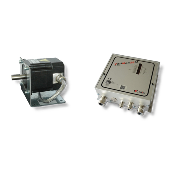
- Page 1 MANUAL Ska vara 25 mm i diameter på höjden CONTROL UNIT FOR ROTATING HEAT EXCHANGER WITH MODBUS VariMax25M UL/CSA Article no. F21025304 control...
-
Page 3: Table Of Contents
TABLE OF CONTENTS Installation instructions Modbus Mounting Technical data, Modbus Safety instructions Connection Manufacturer's declaration Function settings, Modbus Description of functions Operational indications, Modbus Technical data, control unit Timeout Technical data, motor DIP switch Functions Modbus Register Folder - DIP switch Coil - Operational indications Discrete input... -
Page 4: Installation Instructions
INSTALLATION INSTRUCTIONS Warning indication The control unit must only be used in perfect technical condition. Any damage that may affect safety must be dealt with immediately. Maintenance/Repairs The function of the control unit should be checked regularly. Troubleshooting and repairs must only be performed by trained personnel. -
Page 5: Safety Instructions
SAFETY INSTRUCTIONS The following symbols and references will be used in this description. These instructions are important; they apply to personal and technical safety during operation. This safety instruction refers to instructions whose specific intent is to avoid the risk of personal injury and to prevent damage to equipment. -
Page 6: Manufacturer's Declaration
MANUFACTURER'S DECLARATION Manufacturer IBC control AB Brännerigatan 5 A, SE-263 37 Höganäs, Sweden Product Control unit for rotating heat exchanger Type designation VariMax25M EU Directive The manufacturer's declaration of conformity with the requirements of the applicable to the EMC Directive 2004/108/EC. product All control units are approved according to the requirements of the EMC Directive 2004/108/EC and are tested according to standard... -
Page 7: Description Of Functions
DESCRIPTION OF FUNCTIONS • The VariMax25M is a control device with embedded Modbus communication. Technical data for Modbus can be found on page 13-26. The control function can also be used with a normal 0-10 V input signal. Refer to page 6-11. •... -
Page 8: Technical Data, Control Unit
TECHNICAL DATA, CONTROL UNIT External power supply 1x230-240 V +/-15 % Output frequency 0-290 Hz 50/60 Hz Acceleration and 30 sec Power input, max. 110 W retardation time Ambient temperature, Input current, max. 0,9 A -30 - +45 non condensing -40 - +45 C ***) External fuse, max. -
Page 9: Dip Switch
DIP SWITCH Cleaning function Cleaning function connected in ON position. When the rotor has stopped for 10 minutes, the cleaning function is activated and the rotor starts to rotate. As a warning, the rotor first rotates for 6 seconds at a motor speed of 5 rpm, the rotor is then stationary for 3 seconds. -
Page 10: Settings Via Potentiometer
Continued from previous page Probable fault cause - Magnet turned the wrong way during installation - Magnet transmitter incorrectly connected (wrong polarity), refer to "connections" on page 9 - Gap too wide between the magnetic sensor and magnet; max 15 mm Probable fault cause in - Broken belt operation... -
Page 11: Connection Diagram
CONNECTION DIAGRAM (Max 2 A / 50 V AC) 11 12 14 15 A1 A2 9 10 Reset 1 x 230 V Alarm relay Manual Input Rotation Thermal Stepping motor 3-phase speed signal monitor contact 0 - 10 V CONNECTIONS The voltage must be switched off before undertaking any work on the equipment. -
Page 12: Input Signal/Rotation Speed
INPUT SIGNAL/ROTATION SPEED Rotation speed (%) Input signal - rotation speed The input signal is directly proportional to the efficacy of the rotor, which implies that input signal and rotation speed are as per the adjacent diagram. Input signal 0-10 V CHECKS BEFORE POWERING UP THE CONTROL UNIT Check that the control unit is connected as per instructions on page 9. -
Page 13: Emc Installation
EMC INSTALLATION NCY-HAR/UL/CSA 7G0,75 Incoming EKK 3G1.5 Unshielded Shielded Input signal, LiYCY 2x0,34, UL recognized, LiYCY 2x0,34/0,5 UL recognized Shielded Shielded EMC glands must be used for shielded cables. The above cables or equivalent must be used to comply with the EMC Directive. EMC GLAND NOTE! When connecting the shielding to the EMC gland, it is important to connect as shown above. -
Page 17: Modbus
TECHNICAL DATA, MODBUS Communication MODBUS RTU protocol Interface RS485, half-duplex Data rate 9 600, 19 200, 38 400, 56 000 bits per second Bit format 8 databits, 1 stop bit, even parity 8 databits, 1 stop bit, no parity 8 databits, 2 stop bits, no parity 8 databits, 1 stop bit, odd parity Address 8 unique addresses, refer to the table "Addressing"... -
Page 18: Function Settings, Modbus
FUNCTION SETTINGS, MODBUS Activation of Modbus communication and configuration of address, data transfer rate, parity and termination are achieved through a 9-pole DIP switch. On delivery of the unit all DIP switches are set to their OFF position. For setting and configuration of the DIP switches refer to the table on page 18. Modbus communication is activated through DIP switches. -
Page 19: Operational Indications
Green LED Red LED DIP switch OPERATIONAL INDICATIONS, MODBUS Green LED Red LED Operating mode Troubleshooting Unlit Unlit Modbus turned off Unlit Lit with fixed No communication - Communication cable broken light or not connected. - No communication received from host system. Unlit Flashing Non-interpretable... -
Page 20: Dip Switch
DIP SWITCH Modbus communication On Addressing Hexadecimal Decimal Rate 9 600 19 200 38 400 56 000 Package 1 stop bit, even parity 1 stop bit, no parity 2 stop bits, no parity 1 stop bit, odd parity Termination To... -
Page 21: Modbus Register Folder
MODBUS REGISTER FOLDER VariMax25M supports the following Modbus functions: ◆ Coil (digital Read/Write) ◆ Discrete input (digital Read) ◆ Input register (analogue Read) ◆ Holding register (analogue Read/Write) COIL 1-bit register (Read/Write). Modbus function 01 "Read Coil Status" is used for reading. Modbus function 05 "Force Single Coil"... -
Page 22: Discrete Input
DISCRETE INPUT 1-bit status register (Read). Modbus function 02 "Read Input Status" is used for reading. Reads 1 if a fault has occurred. 0 = normal 1 = alarm Address Name Designation Data Read/ Factor Unit form Write Error Error regardless of which fault Single bit Read has occurred. - Page 23 Continued from previous page Address Name Designation Data Read/ Factor Unit form Write Short circuit Short circuit Single bit Read Short circuit Imbalance between phases Single bit Read Short circuit Phase 1 missing Single bit Read Short circuit Phase 2 missing Single bit Read Short circuit Phase 3 missing...
-
Page 24: Input Register 16-Bit
INPUT REGISTER 16-bit register (Read). Modbus function 04 "Read Input Registries" is used for reading. Address Name Designation Data Read/ Factor Unit form Write Program version UINT 16 Read Program version UINT 16 Read VariMax model Reads 25 for VariMax25 etc. UINT 16 Read Temperature Temperature in the control unit INT 16... - Page 25 Continued from previous page Address Name Designation Data Read/ Factor Unit form Write Current rotor Only calculated if the speed UINT 16 Read speed reference value remains constant between two pulses on the rotation monitor. Displays 0 if no value is available. To ensure the correctness of the measured value the speed reference value should be...
-
Page 26: Input Register 32-Bit
INPUT REGISTER 32-bit register (Read). Modbus function 04 "Read Input Registries" is used for reading. Address Name Designation Data Read/ Factor Unit form Write Motor speed RPM Number of rotations UINT 32 Read Motor starts Number of motor starts UINT 32 Read Restarts Number of faults causing restarts UINT 32 Read Surge... - Page 27 Continued from previous page Address Name Designation Data Read/ Factor Unit form Write Stop time, Time with stopped motor, UINT 32 Read normal temp. 0-40 °C Stop time, Time with stopped motor, UINT 32 Read cold temp. below 0 °C Running time, Time with motor running, in UINT 32 Read...
-
Page 28: Holding Register
HOLDING REGISTER 16-bit register (Read/Write). Modbus function 03 "Read Holding Registries" is used for Reading. Modbus function 06 "Write Singles Registries" is used for Writing. Address Name Designation Data Read/ Factor Unit form Write Reference value, 1000 = 100 % of max speed UINT 16 Read/ relative speed setting. -
Page 29: Personal Notes
PERSONAL NOTES... - Page 30 PERSONAL NOTES...
- Page 31 PERSONAL NOTES...
- Page 32 IBC control AB Brännerigatan 5 A SE-263 37 Höganäs Sweden Tel. +46 42 33 00 10 www.ibccontrol.se info@ibccontrol.se...
- Page 33 MANUAL Ska vara 25 mm i diameter på höjden CONTROL UNIT FOR ROTATING HEAT EXCHANGER WITH MODBUS VariMax50M UL/CSA Article no. F21050304 control...
- Page 35 TABLE OF CONTENTS Installation instructions Modbus Mounting Technical data, Modbus Safety instructions Connection Manufacturer's declaration Function settings, Modbus Description of functions Operational indications, Modbus Technical data, control unit Timeout Technical data, motor DIP switch Functions Modbus Register Folder - DIP switch Coil - Operational indications Discrete input...
-
Page 36: Installation Instructions
INSTALLATION INSTRUCTIONS Warning indication The control unit must only be used in perfect technical condition. Any damage that may affect safety must be dealt with immediately. Maintenance/Repairs The function of the control unit should be checked regularly. Troubleshooting and repairs must only be performed by trained personnel. -
Page 37: Safety Instructions
SAFETY INSTRUCTIONS The following symbols and references will be used in this description. These instructions are important; they apply to personal and technical safety during operation. This safety instruction refers to instructions whose specific intent is to avoid the risk of personal injury and to prevent damage to equipment. -
Page 38: Manufacturer's Declaration
MANUFACTURER'S DECLARATION Manufacturer IBC control AB Brännerigatan 5 A, SE-263 37 Höganäs, Sweden Product Control unit for rotating heat exchanger Type designation VariMax50M EU Directive The manufacturer's declaration of conformity with the requirements of the applicable to the EMC Directive 2004/108/EC. product All control units are approved according to the requirements of the EMC Directive 2004/108/EC and are tested according to standard... -
Page 39: Description Of Functions
DESCRIPTION OF FUNCTIONS • The VariMax50M is a control device with embedded Modbus communication. Technical data for Modbus can be found on page 13-26. The control function can also be used with a normal 0-10 V input signal. Refer to page 6-11. •... -
Page 40: Technical Data, Control Unit
TECHNICAL DATA, CONTROL UNIT External power supply 1x230-240 V +/-15 % Output frequency 0-312 Hz 50/60 Hz Acceleration and 30 sec Power input, max. 240 W retardation time Ambient temperature, Input current, max. 1,9 A -30 - +45 non condensing -40 - +45 C ***) External fuse, max. -
Page 41: Dip Switch
DIP SWITCH Cleaning function Cleaning function connected in ON position. When the rotor has stopped for 10 minutes, the cleaning function is activated and the rotor starts to rotate. As a warning, the rotor first rotates for 6 seconds at a motor speed of 5 rpm, the rotor is then stationary for 3 seconds. -
Page 42: Settings Via Potentiometer
Continued from previous page Probable fault cause - Magnet turned the wrong way during installation - Magnet transmitter incorrectly connected (wrong polarity), refer to "connections" on page 9 - Gap too wide between the magnetic sensor and magnet; max 15 mm Probable fault cause in - Broken belt operation... -
Page 43: Connection Diagram
CONNECTION DIAGRAM (Max 2 A / 50 V AC) 11 12 14 15 A1 A2 9 10 Reset 1 x 230 V Alarm relay Manual Input Rotation Thermal Stepping motor 3-phase speed signal monitor contact 0 - 10 V CONNECTIONS The voltage must be switched off before undertaking any work on the equipment. -
Page 44: Input Signal/Rotation Speed
INPUT SIGNAL/ROTATION SPEED Rotation speed (%) Input signal - rotation speed The input signal is directly proportional to the efficacy of the rotor, which implies that input signal and rotation speed are as per the adjacent diagram. Input signal 0-10 V CHECKS BEFORE POWERING UP THE CONTROL UNIT Check that the control unit is connected as per instructions on page 9. -
Page 45: Emc Installation
EMC INSTALLATION NCY-HAR/UL/CSA 7G0,75 Incoming EKK 3G1.5 Unshielded Shielded Input signal, LiYCY 2x0,34, UL recognized, LiYCY 2x0,34/0,5 UL recognized Shielded Shielded EMC glands must be used for shielded cables. The above cables or equivalent must be used to comply with the EMC Directive. EMC GLAND NOTE! When connecting the shielding to the EMC gland, it is important to connect as shown above. -
Page 49: Modbus
TECHNICAL DATA, MODBUS Communication MODBUS RTU protocol Interface RS485, half-duplex Data rate 9 600, 19 200, 38 400, 56 000 bits per second Bit format 8 databits, 1 stop bit, even parity 8 databits, 1 stop bit, no parity 8 databits, 2 stop bits, no parity 8 databits, 1 stop bit, odd parity Address 8 unique addresses, refer to the table "Addressing"... -
Page 50: Function Settings, Modbus
FUNCTION SETTINGS, MODBUS Activation of Modbus communication and configuration of address, data transfer rate, parity and termination are achieved through a 9-pole DIP switch. On delivery of the unit all DIP switches are set to their OFF position. For setting and configuration of the DIP switches refer to the table on page 18. Modbus communication is activated through DIP switches. -
Page 51: Operational Indications, Modbus
Green LED Red LED DIP switch OPERATIONAL INDICATIONS, MODBUS Green LED Red LED Operating mode Troubleshooting Unlit Unlit Modbus turned off Unlit Lit with fixed No communication - Communication cable broken light or not connected. - No communication received from host system. Unlit Flashing Non-interpretable... -
Page 52: Dip Switch
DIP SWITCH Modbus communication On Addressing Hexadecimal Decimal Rate 9 600 19 200 38 400 56 000 Package 1 stop bit, even parity 1 stop bit, no parity 2 stop bits, no parity 1 stop bit, odd parity Termination To... -
Page 53: Modbus Register Folder
MODBUS REGISTER FOLDER VariMax50M supports the following Modbus functions: ◆ Coil (digital Read/Write) ◆ Discrete input (digital Read) ◆ Input register (analogue Read) ◆ Holding register (analogue Read/Write) COIL 1-bit register (Read/Write). Modbus function 01 "Read Coil Status" is used for reading. Modbus function 05 "Force Single Coil"... -
Page 54: Discrete Input
DISCRETE INPUT 1-bit status register (Read). Modbus function 02 "Read Input Status" is used for reading. Reads 1 if a fault has occurred. 0 = normal 1 = alarm Address Name Designation Data Read/ Factor Unit form Write Error Error regardless of which fault Single bit Read has occurred. - Page 55 Continued from previous page Address Name Designation Data Read/ Factor Unit form Write Short circuit Short circuit Single bit Read Short circuit Imbalance between phases Single bit Read Short circuit Phase 1 missing Single bit Read Short circuit Phase 2 missing Single bit Read Short circuit Phase 3 missing...
-
Page 56: Input Register 16-Bits
INPUT REGISTER 16-bit register (Read). Modbus function 04 "Read Input Registries" is used for reading. Address Name Designation Data Read/ Factor Unit form Write Program version UINT 16 Read Program version UINT 16 Read VariMax model Reads 50 for VariMax50 etc. UINT 16 Read Temperature Temperature in the control unit INT 16... - Page 57 Continued from previous page Address Name Designation Data Read/ Factor Unit form Write Current rotor Only calculated if the speed UINT 16 Read speed reference value remains constant between two pulses on the rotation monitor. Displays 0 if no value is available. To ensure the correctness of the measured value the speed reference value should be...
-
Page 58: Input Register 32-Bit
INPUT REGISTER 32-bit register (Read). Modbus function 04 "Read Input Registries" is used for reading. Address Name Designation Data Read/ Factor Unit form Write Motor speed RPM Number of rotations UINT 32 Read Motor starts Number of motor starts UINT 32 Read Restarts Number of faults causing restarts UINT 32 Read Surge... - Page 59 Continued from previous page Address Name Designation Data Read/ Factor Unit form Write Stop time, Time with stopped motor, UINT 32 Read normal temp. 0-40 °C Stop time, Time with stopped motor, UINT 32 Read cold temp. below 0 °C Running time, Time with motor running, in UINT 32 Read...
-
Page 60: Holding Register
HOLDING REGISTER 16-bit register (Read/Write). Modbus function 03 "Read Holding Registries" is used for Reading. Modbus function 06 "Write” Singles Registries" is used for Writing. Address Name Designation Data Read/ Factor Unit form Write Reference value, 1000 = 100 % of set max rpm UINT 16 Read/ relative speed speed. -
Page 61: Personal Notes
PERSONAL NOTES... - Page 62 PERSONAL NOTES...
- Page 63 PERSONAL NOTES...
- Page 64 IBC control AB Brännerigatan 5 A SE-263 37 Höganäs Sweden Tel. +46 42 33 00 10 www.ibccontrol.se info@ibccontrol.se...
- Page 65 MANUAL Ska vara 25 mm i diameter på höjden CONTROL UNIT FOR ROTATING HEAT EXCHANGER WITH MODBUS VariMax100M UL/CSA Article no. F21100304 control...
- Page 67 TABLE OF CONTENTS Installation instructions Modbus Mounting Technical data, Modbus Safety instructions Connection Manufacturer's declaration Function settings, Modbus Description of functions Operational indications, Modbus Technical data, control unit Timeout Technical data, motor DIP switch Functions Modbus Register Folder - DIP switch Coil - Operational indications Discrete input...
-
Page 68: Installation Instructions
INSTALLATION INSTRUCTIONS Warning indication The control unit must only be used in perfect technical condition. Any damage that may affect safety must be dealt with immediately. Maintenance/Repairs The function of the control unit should be checked regularly. Troubleshooting and repairs must only be performed by trained personnel. -
Page 69: Safety Instructions
SAFETY INSTRUCTIONS The following symbols and references will be used in this description. These instructions are important; they apply to personal and technical safety during operation. This safety instruction refers to instructions whose specific intent is to avoid the risk of personal injury and to prevent damage to equipment. -
Page 70: Manufacturer's Declaration
MANUFACTURER'S DECLARATION Manufacturer IBC control AB Brännerigatan 5 A, SE-263 37 Höganäs, Sweden Product Control unit for rotating heat exchanger Type designation VariMax100M EU Directive The manufacturer's declaration of conformity with the requirements of the applicable to the EMC Directive 2004/108/EC. product All control units are approved according to the requirements of the EMC Directive 2004/108/EC and are tested according to standard... -
Page 71: Description Of Functions
DESCRIPTION OF FUNCTIONS • The VariMax100M is a control device with embedded Modbus communication. Technical data for Modbus can be found on page 13-26. The control function can also be used with a normal 0-10 V input signal. Refer to page 6-11. •... -
Page 72: Technical Data, Control Unit
TECHNICAL DATA, CONTROL UNIT External power supply 1x230-240 V +/-15 % Output frequency 0-333 Hz 50/60 Hz Acceleration and 30 sec Power input, max. 500 W retardation time Ambient temperature, Input current, max. 2,2 A -30 - +45 non condensing -40 - +45 C ***) External fuse, max. -
Page 73: Dip Switch
DIP SWITCH Cleaning function Cleaning function connected in ON position. When the rotor has stopped for 10 minutes, the cleaning function is activated and the rotor starts to rotate. As a warning, the rotor first rotates for 6 seconds at a motor speed of 5 rpm, the rotor is then stationary for 3 seconds. -
Page 74: Settings Via Potentiometer
Continued from previous page Probable fault cause - Magnet turned the wrong way during installation - Magnet transmitter incorrectly connected (wrong polarity), refer to "connections" on page 9 - Gap too wide between the magnetic sensor and magnet; max 15 mm Probable fault cause in - Broken belt operation... -
Page 75: Connection Diagram
CONNECTION DIAGRAM (Max 2 A / 50 V AC) 11 12 14 15 A1 A2 9 10 Reset 1 x 230 V Alarm relay Manual Input Rotation Thermal Stepping motor 3-phase speed signal monitor contact 0 - 10 V CONNECTIONS The voltage must be switched off before undertaking any work on the equipment. -
Page 76: Input Signal/Rotation Speed
INPUT SIGNAL/ROTATION SPEED Rotation speed (%) Input signal - rotation speed The input signal is directly proportional to the efficacy of the rotor, which implies that input signal and rotation speed are as per the adjacent diagram. Input signal 0-10 V CHECKS BEFORE POWERING UP THE CONTROL UNIT Check that the control unit is connected as per instructions on page 9. -
Page 77: Emc Installation
EMC INSTALLATION NCY-HAR/UL/CSA 7G0,75 Incoming EKK 3G1.5 Unshielded Shielded Input signal, LiYCY 2x0,34, UL recognized, LiYCY 2x0,34/0,5 UL recognized Shielded Shielded EMC glands must be used for shielded cables. The above cables or equivalent must be used to comply with the EMC Directive. EMC GLAND NOTE! When connecting the shielding to the EMC gland, it is important to connect as shown above. -
Page 81: Modbus
TECHNICAL DATA, MODBUS Communication MODBUS RTU protocol Interface RS485, half-duplex Data rate 9 600, 19 200, 38 400, 56 000 bits per second Bit format 8 databits, 1 stop bit, even parity 8 databits, 1 stop bit, no parity 8 databits, 2 stop bits, no parity 8 databits, 1 stop bit, odd parity Address 8 unique addresses, refer to the table "Addressing"... -
Page 82: Function Settings, Modbus
FUNCTION SETTINGS, MODBUS Activation of Modbus communication and configuration of address, data transfer rate, parity and termination are achieved through a 9-pole DIP switch. On delivery of the unit all DIP switches are set to their OFF position. For setting and configuration of the DIP switches refer to the table on page 18. Modbus communication is activated through DIP switches. -
Page 83: Operational Indications, Modbus
Green LED Red LED DIP switch OPERATIONAL INDICATIONS, MODBUS Green LED Red LED Operating mode Troubleshooting Unlit Unlit Modbus turned off Unlit Lit with fixed No communication - Communication cable broken light or not connected. - No communication received from host system. Unlit Flashing Non-interpretable... -
Page 84: Dip Switch
DIP SWITCH Modbus communication On Addressing Hexadecimal Decimal Rate 9 600 19 200 38 400 56 000 Package 1 stop bit, even parity 1 stop bit, no parity 2 stop bits, no parity 1 stop bit, odd parity Termination To... -
Page 85: Modbus Register Folder
MODBUS REGISTER FOLDER VariMax100M supports the following Modbus functions: ◆ Coil (digital Read/Write) ◆ Discrete input (digital Read) ◆ Input register (analogue Read) ◆ Holding register (analogue Read/Write) COIL 1-bit register (Read/Write). Modbus function 01 "Read Coil Status" is used for reading. Modbus function 05 "Force Single Coil"... -
Page 86: Discrete Input
DISCRETE INPUT 1-bit status register (Read). Modbus function 02 "Read Input Status" is used for reading. Reads 1 if a fault has occurred. 0 = normal 1 = alarm Address Name Designation Data Read/ Factor Unit form Write Error Error regardless of which fault Single bit Read has occurred. - Page 87 Continued from previous page Address Name Designation Data Read/ Factor Unit form Write Short circuit Short circuit Single bit Read Short circuit Imbalance between phases Single bit Read Short circuit Phase 1 missing Single bit Read Short circuit Phase 2 missing Single bit Read Short circuit Phase 3 missing...
-
Page 88: Input Register 16-Bit
INPUT REGISTER 16-bit register (Read). Modbus function 04 "Read Input Registries" is used for reading. Address Name Designation Data Read/ Factor Unit form Write Program version UINT 16 Read Program version UINT 16 Read VariMax model Reads 100 for VariMax100 etc. UINT 16 Read Temperature Temperature in the control unit INT 16... - Page 89 Continued from previous page Address Name Designation Data Read/ Factor Unit form Write Current rotor Only calculated if the speed UINT 16 Read speed reference value remains constant between two pulses on the rotation monitor. Displays 0 if no value is available. To ensure the correctness of the measured value the speed reference value should be...
-
Page 90: Input Register 32-Bit
INPUT REGISTER 32-bit register (Read). Modbus function 04 "Read Input Registries" is used for reading. Address Name Designation Data Read/ Factor Unit form Write Motor speed RPM Number of rotations UINT 32 Read Motor starts Number of motor starts UINT 32 Read Restarts Number of faults causing restarts UINT 32 Read Surge... - Page 91 Continued from previous page Address Name Designation Data Read/ Factor Unit form Write Stop time, Time with stopped motor, UINT 32 Read normal temp. 0-40 °C Stop time, Time with stopped motor, UINT 32 Read cold temp. below 0 °C Running time, Time with motor running, in UINT 32 Read...
-
Page 92: Holding Register
HOLDING REGISTRY 16-bit registry (Read/Write). Modbus function 03 "Read Holding Registries" is used for Reading. Modbus function 06 "Write Singles Registries" is used for Writing. Address Name Designation Data Read/ Factor Unit form Write Reference value, 1000 = 100 % of set max rpm UINT 16 Read/ relative speed speed. -
Page 93: Personal Notes
PERSONAL NOTES... - Page 94 PERSONAL NOTES...
- Page 95 PERSONAL NOTES...
- Page 96 IBC control AB Brännerigatan 5 A SE-263 37 Höganäs Sweden Tel. +46 42 33 00 10 www.ibccontrol.se info@ibccontrol.se...
Need help?
Do you have a question about the F21025304 and is the answer not in the manual?
Questions and answers