Advertisement
Quick Links
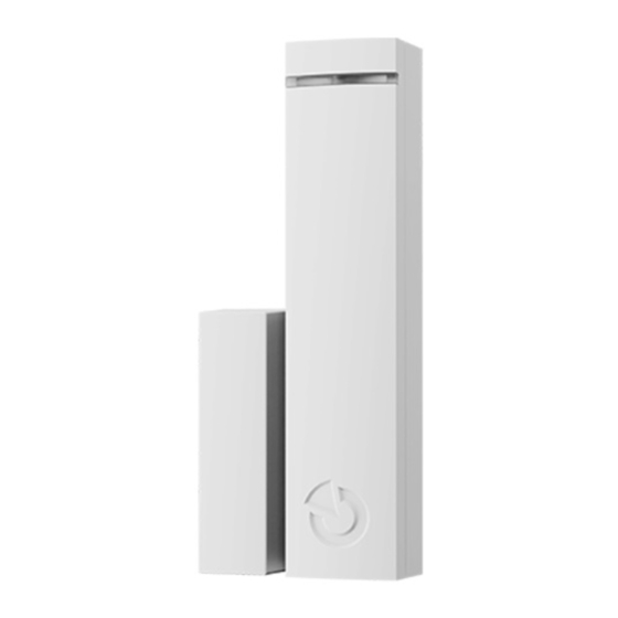
The JA-152SHM wireless shock or tilt detector with magnetic
The product is a wireless component of the JABLOTRON system.
It is a combined shock or tilt detector with external input. It occupies two
separate enrolment addresses in the control panel. The product can be
installed by a trained technician with a valid certificate issued by an authorized
distributor.
The product is compatible with the JA-103K, JA-107K or above.
Installation
It is always necessary to have a look at how the detector is used.
We do not recommend installing the detector directly onto metal surface
that can negatively affect wireless communication with a control panel.
The detector responds to vibrations and shocks caused by the pad to
which it is mounted when the shock mode is selected. The mechanical
contact must be sufficient for a good transmission of shocks to
the detector. The detector should be placed in locations where stronger
shocks are expected – i. e. further away from fixed edges of windows or
door frames.
When in a tilt mode, the detector reacts to a change in its position. –
e. g. on a window casement.
There are two different types of permanent magnets in the package –
a standard magnet in a plastic housing (A) and a ring-shaped magnet (B)
for use in places where there is not enough space for a standard magnet
or for counter-sinking the magnet into a door or window's inner frame.
The detector activation distance threshold (only applicable to non-
ferromagnetic installation surfaces) is 26 / 17 mm for the Z axis. For other
types of magnets, the detection threshold characteristic may vary.
Figure: 1 – place for locking screw, 2 – cover tab, 3 – LED indication,
4 – battery, 5 – serial number, 6 – terminals, 7 – cover tamper contact
Axis
Activation distance (mm)
Deactivation distance (mm)
Table 1: distances for opening and closing on a non-magnetic base.
Axis
Activation distance (mm)
Deactivation distance (mm)
Table 2: distances for opening and closing on the magnetic base.
1.
Open the detector cover by pressing the cover tab (2).
2.
Mount the rear pad onto the required place. If it´s needed, put
the cables through the rear plastic pad. The length of cables to
the detector should not exceed 3 m; choose the place of installation
accordingly.
3.
Attach the selected magnet to the moving part of the door (window)
with screws. The lower edge of the standard magnet has to be at
the same height as the lower edge of the detector. It is recommended
to attach the whorl-shaped magnet with a non-magnetic screw from
the package.
JA-152SHM
contact
4.
5.
6.
7.
8.
Notes:
allows you to change the internal settings remotely and at the same times
does not consume a lot of battery capacity.
mode, until the service mode is exited (but no longer than 24 h). In this
mode, the detector checks every 90s whether system is still in service
mode or if new settings should be taken over.
with each activation. Therefore, when switching from operational mode to
service mode, it can take up to 19 minutes for the detector to recognize
control panel status or internal settings change. This period can be
reduced by activating the detector or its tamper sensor.
Please note:
delivery of the new setting, when changes are applied. System
remembers the requested change and forwards the new settings to
the detector during the next period of regular communication.
software. Click on the Internal settings button at the detector's position
to open a dialogue window where you set (* indicates default settings):
Input 1
shocks for 10 seconds. After this 10 s, there will be a 30 s interval in which
the next possible jolt will be reported as an Input Activation. If no further
shocks occur within these 30 s, the 1st shock will be ignored - no Input
Activation will be reported in the system. By disabling the option, the
detector sends an Input Activation to the system as soon as the 1st shock
X
Y
Z
is detected.
13
27
27
Sensitivity: Detector sensitivity level. The detector ignores jolts/tilts that
7
21
20
do not exceed the sensitivity setting. Automatic shock sensitivity
adjustment: how to adjust the sensitivity:
X
Y
Z
Service mode, then Activate tamper contact (open the plastic cover) and
13
28
28
within 5 seconds deactivate the tamper contact (close the plastic cover).
9
19
21
indication as described below from point 3. When starting calibration from
the detector, the Yellow LED will not be lit (it is only lit if the peripheral has
an open internal setting in the F-Link). Calibration can be terminated by
activating the tamper contact (open the plastic cover).
1 / 2
Connect the wires from external contact to the terminals, if they are
used.
Proceed according to the control panel installation manual.
Basic procedure:
a.
In the F-link software, select the required position in
the Devices window and launch the enrolment mode by
clicking on the Enrol option.
b.
Insert the battery (mind the correct polarity). The enrolment
signal is transmitted when the battery is inserted into
the detector. Note – the detector occupies 2 positions (each
input has its own position). Should the second position be
occupied, it will be automatically overwritten.
Close the detector cover.
In order to comply with norms, the front cover must be secured with
the supplied locking screw (1).
Configure the detector by following the Internal settings chapter in
this manual.
−
The detector can also be enroled into the system by entering its
serial number (5) into the F-link software (1400-00-0000-0001).
You can find the sticker with serial number under a bar code,
located on the battery holder.
−
If only the first input is used, the second input can be deleted by
pressing "Delete" to release the position for another device.
−
By deleting the first input position, the module will be deleted
completely.
Detector communication in the system
The detector uses bi-directional asynchronous communication which
After enrolment to the system, the detector operates in an accelerated
In service mode, the detector communicates once every 19 minutes or
It is not necessary to wait 90 s (or 19 min) until the detector confirms
Internal settings
The detector settings can be set in the Devices tab of the F-link
- Function: Shock* / Tilt / Disabled
Shock: The device responds to environmental shock input.
Activation of shock:
Turning on the detector option after the 1st shock will ignore any further
To start the calibration from the peripheral, the system must be in
This procedure will switch on calibration directly from the peripheral -
1.
LED off = detector waiting for connection. To continue, activate
the magnet (open and close the window/door)..
2.
Yellow
LED
illuminated
a connection. Start calibration to continue.
3.
Glow yellow LED + regular double red LED = detector is ready
to start calibration. Activate magnet to continue.
=
detector
has
established
MLB55202
Advertisement

Related Manuals for jablotron JA-152SHM


Summary of Contents for jablotron JA-152SHM
- Page 1 The JA-152SHM wireless shock or tilt detector with magnetic contact Connect the wires from external contact to the terminals, if they are The product is a wireless component of the JABLOTRON system. used. It is a combined shock or tilt detector with external input. It occupies two separate enrolment addresses in the control panel.
- Page 2 The JA-152SHM wireless shock or tilt detector with magnetic contact Glow of yellow LED + rapid blinking of red LED = detector Technical specification calibration for approx. 4 s. Please calm the magnetic detector. Power 1x alkaline battery type LR6 AA (1.5 V/2.4 Ah)
Need help?
Do you have a question about the JA-152SHM and is the answer not in the manual?
Questions and answers