Table of Contents
Advertisement
Quick Links
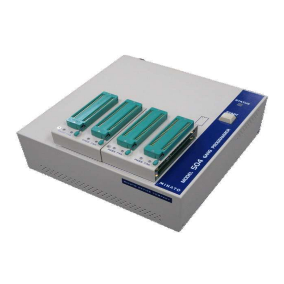
MODEL500 SERIES PROGRAMMER
Revision
2016/09/29
Rev.1.00
2017/02/03
Rev.2.00
2017/04/08
Rev.3.00
2017/04/12
Rev.4.00
2017/06/16
Rev.5.00
2017/09/22
Rev.6.00
2018/05/09
Rev.7.00
2018/05/09
Rev.8.00
2018/02/15
Rev.9.00
2019/10/29
Rev.10.00
2022/01/17
Rev.11.00
2022/06/30
Rev.12.00
OPERATION MANUAL
Corrected description of connected USB during hardware setup
(USB2.0->USB3.0)
Corrected typographical error in the operation after power on.
Added description of how to upgrade software version.
Corrected Recommended PC requirements. Added specifications and
photos of M504,M508.
Added about Protect function.
Name change of company.
Added the note that project file created in M400 programmer can be
used.
Name change of company.
Added the description of eMMC 4 sockets unit in Module chapter.
Added the note about operation of module.
Added the description of new function and note about load file/save buffer.
Added Windows10 to OS requirements.
Added FPGA update behaviour.
Change of business address.
Added note on Self test execution.
Advertisement
Table of Contents

Related Manuals for MINATO 500 Series

Summary of Contents for MINATO 500 Series
- Page 1 OPERATION MANUAL MODEL500 SERIES PROGRAMMER Revision 2016/09/29 Rev.1.00 2017/02/03 Rev.2.00 Corrected description of connected USB during hardware setup (USB2.0->USB3.0) 2017/04/08 Rev.3.00 Corrected typographical error in the operation after power on. 2017/04/12 Rev.4.00 Added description of how to upgrade software version. 2017/06/16 Rev.5.00 Corrected Recommended PC requirements.
-
Page 2: Preview
Preview Preview Dear Customer, We are pleasure to see you purchasing Minato Gang Programmer MODEL500 Series. This manual explains how to use MODEL500 Series correctly, so please read this manual before operation. Register for Warranty MINATO ADVANCED TECHNOLOGIES INC. will implement support for our products, please register all the information on our web. -
Page 3: Pc Requirements For Control Model500
PC Requirements for control MODEL500 PC Requirements for control MODEL500 OS requirements Windows Vista Windows 7 ( 32bit, 64bit ) Windows 8, 8.1 ( 32bit, 64bit ) Windows10 Recommended PC requirements CPU 32bit(x86)or64bit(x64) 1GHz or Higher If possible, dual core or higher performance CPU is recommended. -
Page 4: Simple Guide
Simple Guide Simple Guide Preview ・・・・・・ 27 Installation ・・・・・・ 27 Software ・・・・・・ 30 Hardware ・・・・・・ 33 Notice for first time connecting to PC Hardware Software ・・・3 ・・・35 PC Requirements Outline ・・・15 ・・・35 Outline Outline Outline ・・・36 ... -
Page 5: Model500 Series Packing List
MODEL500 Series Packing list Before installing your programmer, please carefully check that your package include all next mentioned parts. If you find any discrepancy or if any of these items are damaged, please contact distributor or Minato directly. [Packing list] MODEL500 Series (MODEL504*, MODEL508*, MODEL516) ... -
Page 6: Warranty Terms
Warranty Terms Warranty Terms Minato gives a guarantee on programmer for one-year from the date of purchase (Just for customer who has registered their programmer). The warranty does not apply to products on some conditions, so please read below contents. -
Page 7: Special Notes
2. You should pay for the transportation fee from you to Mianto. 3. Please keep the box provided by Minato which can be reused while transportation for repair. Please make sure the package is strong, otherwise you should pay for the damage of programmer. -
Page 8: Maintainance Of M500 Series
About repair, calibration and version up Minato does not provide on-the-spot service no matter free charge or not. And we can not provide spare programmer, please understand. Customer should pay for the transportation fee from you to minato for repair, calibration and version up. Minato will bear the transportation cost for return. -
Page 9: Safety Precaution
Contents Safety Precaution Warning and Cautions This operation manual includes safety precautions for safely use M500 Series programmer. To prevent the operator or others people from injury and property damage, please following below pictographs to operate. Before reading this manual, fully understand these pictographs and the meanings. Keep this manual at hand and refer to it while necessary. - Page 10 If the programmer is dropped or shocked, please remove the power plug immediately. Otherwise it may cause a fire or electric shock due to short-circuit. Consult with Minato or distributor. Unplug Power Cord If any liquid or foreign matter enters the programmer, please remove the power plug immediately.
- Page 11 Contents Cautions The operator should fully understand the manual before operation. Miss operation may damage the programmer or ICs. Compulsion Before touching the programmer, please touch a nearby large metal to remove static electricity from your body. Static electricity may damage the programmer or ICs. Compulsion Please clean the surfaces, the socket and the air filter screen of programmer.
-
Page 12: Contents
Contents Caution for accessories Standard power cable complies with Japanese regulation. If you will use this programmer in others country, please follow the local safety Standard. Compulsion Before you execute Programmer Self test, please remove device and adapter from socket unit. Otherwise device or adapter might be damaged. -
Page 13: Table Of Contents
Contents Contents Contents PREVIEW ............................2 PC REQUIREMENTS FOR CONTROL MODEL500 ..............3 SIMPLE GUIDE ..........................4 MODEL500 SERIES PACKING LIST .................... 5 WARRANTY TERMS ........................6 Warranty Period ..........................6 Warranty Items ..........................6 Pay for repair ..........................6 Exempt of Warranty ........................ - Page 14 Contents NOTICE FOR FIRST TIME CONNECTING TO PC ..............33 MODEL500 SERIES CONTROL SOFTWARE ( UNIVERSAL CONTROL PROGRAM ) ..35 Outline ............................35 Start Running the Universal Control Program ................36 Description of the main screen ..................... 38 BASIC OPERATION ........................51 Select Device ..........................
-
Page 15: Outline
Outline Outline Outline M500 Series are Gang Programmer which can be controlled by PC (windows OS) software through USB Port. It is also can be used independently as program files has been saved in the independent version. (The independent version hasn't been launched on market.) M500 Series are equipped with 128GByte (1024Gbit) Buffer Memory and can flexibly support advanced PROM IC devices with large capacity, specially designed for small... -
Page 16: Model500 Series Element And Function
In order to operate MODEL500 Series properly, please understand the function of each part and its name.The details are described in following pages. When used, MODEL 500 series of products shall be accompanied by dedicated control software and socket unit. Please note that the startup would fail if software other than special control software is used. -
Page 17: Module Position
FA IL PASS FA IL PASS FA IL PASS FA IL SATA9 SATA10 SATA11 SATA12 SATA13 SATA14 SATA15 SATA16 MINATO MINATO PASS FA IL PASS FA IL PASS FA IL PASS FA IL PASS FA IL PASS FA IL PASS... -
Page 18: Rear Panel
Side Panel Rear Panel USB connector INPUT:100V-240V 4.0A 50-60Hz POWER WARNING! This is class A product. In a domestic environment, This product may cause radio interference in which case the user may be required to take adequate measures. Power Air Vent Power Switch Connector Power Connector... - Page 19 Rear Panel Side Panel Air vent Revision number Serial number Air vent Air vent is designed for the external air sucked for cooling the interior of MODEL500 series. Please keep the vent unblocked. Please use dust collector etc. to remove apparent dust (if any) in air filter.
-
Page 20: Module
Side Panel Module 48pin socket PASS FA IL PASS FA IL PASS/FAIL LED Installed on PC and equipped with IC or adapter. The PC is equipped with a module with 48pin socket. Pay attention to the following content when installing the module on PC. ... - Page 21 Rear Panel 4 sockets unit is provided for eMMC as option module. Maximum 32 devices can be programmed simultaneously in M516. Please select the suitable adaptor for device. M500-011A-K6...
-
Page 22: Optional Items
About Various Adapters Optional Items MODEL 500 series of products are supplied with standard socket unit (48Pin DIP). In addition to standard socket unit, user may optionally use the following socket units and adapters. Please make sure the socket unit and adapter are matched with the device used. -
Page 23: About Various Adapters
About Various Adapters About Various Adapters Various adapters Adapters can be using in corresponding software of M1940,M1950,M400 can also be used in M500 series. ※Refer to “About Adapter” for details. M500-011A-K6... -
Page 24: About Adapter
FAIL PASS FAIL PASS FAIL PASS FAIL PASS FAIL PASS FAIL PASS FAIL SATA9 SATA10 SATA11 SATA12 SATA13 SATA14 SATA15 SATA16 MINATO MINATO PASS FAIL PASS FAIL PASS FAIL PASS FAIL PASS FAIL PASS FAIL PASS FAIL PASS FAIL M500-011A-K6... - Page 25 About Adapter M500-011A-K6...
- Page 26 About Installation (Software and Hardware) Matters needing attention when connecting MODEL500 series of ※ products to PC for the first time (Important ) M500-011A-K6...
-
Page 27: Installation
Installation Installation The CD-ROM contains M500 Series Control software (Universal Control Program), USB drive and operation manual. In order to control the programmer by software, you must correctly install the USB driver and software first. ※The software must be installed before connecting the programmer with PC. Installation of Software Please insert the CD-ROM to install below software. - Page 28 Installation Creating a short-cut on the desktop after selecting Auto installation This screen means the installation has been finished. Please click (finish) ※ Installing the USB_driver.exe by the same method. M500-011A-K6...
- Page 29 Installation ※ Note ※ When running the applications developed by using [Visual C++ 2010], the installation packet is required. If your PC cannot install [Visual C++ 2010] or above, please install [vcredist_x86.exe]. For smooth installation, the following OS are required. Windows XP Service Pack3 or above Windows Vista Service Pack2 or above Windows 7...
-
Page 30: Installation For Hardware
Installation Installation for Hardware Before start the Universal Control Program, please connecting M500 Series to PC by USB cable. Windows will detect new hardware, please follow below method to install the driver. M500 Series will be detected by windows and installation will start automatically. Please insert the CD-ROM. - Page 31 Installation Confirming the installation. Please select continue. M500-011A-K6...
- Page 32 Click “Finish” button to finish the setup. ※ Notice ※ In addition, MODEL 500 series of products will detect the new hardware in the connected unit (COM port), and programmers M516 and M508 will perform hardware installation for 4 times and 2 times, respectively.
-
Page 33: Notice For First Time Connecting To Pc
Notice for first time connecting to PC Notice for first time connecting to PC After installing the hardware driver Please perform the following operations when using Windows XP (SP3). Where the following operation is not performed, PC would be unable to identify MODEL500 series of products. - Page 34 M500 Series Control Software (Universal Control Program) Operation Manual This chapter explains how to use this Universal Control Program of M500 Series. This Control Software will be updated without giving notice due to improvement. Any effects will be fixed by new software. M500-011A-K6...
-
Page 35: Model500 Series Control Software ( Universal Control Program )
MODEL500 Series Control Software (Universal Control Program) MODEL500 Series Control Software ( Universal Control Program ) Outline M500 Series Control Software is suitable for MODEL504, MODEL508, MODEL516. Main features: ① MODEL504, MODEL508, MODEL516 can be controlled by the same software. ②... -
Page 36: Start Running The Universal Control Program
MODEL500 Series Control Software (Universal Control Program) Start Running the Universal Control Program After installation was finished, please double click the icon on the desktop. And below dialog box will display. [ Connect a programmer Dialog box ] Automatically detect and connect the programmer (Online mode) On the dialog box [Connect a programmer], choose [Connect] and click [Select]. - Page 37 MODEL500 Series Control Software (Universal Control Program) On the dialog box [Connect a programmer], choose [Model 516] and click [Select], the control software will be forced to MODEL 516 Demo mode and [DEMO] will be showed on the main screen of software. AutoHandler mode On the dialog box [Connect a programmer], choose [Use handler] and click [Select], the control software will be forced to handler mode and the status of programmer is...
-
Page 38: Description Of The Main Screen
MODEL500 Series Control Software (Universal Control Program) Description of the main screen Here will introduce the function of the main screen and the sample is MODEL500 (It’s the same for MODEL508 and MODEL516 except the programmer’s Model.) Description of the main screen(MODEL516 Main Screen) ①Title bar ③Tool bar ②Menu bar... - Page 39 MODEL500 Series Control Software (Universal Control Program) [File] 「Load Project..」 「Save Project..」 「Load file to buffer」 「Save buffer to file」 「Config」(Initial setup for system and password is required) 「Control of a log file」(Setting of log file) ...
- Page 40 MODEL500 Series Control Software (Universal Control Program) [Edit] 「Edit buffer」 M500-011A-K6...
- Page 41 MODEL500 Series Control Software (Universal Control Program) [Programmer] 「Buzzer」 「Self test」 「Clear data」 (clear the BufferData of programmer) 「File list」 (File list in buffer) 「LED check」 「Handler position」(For Auto Handler: Number the programmers) M500-011A-K6...
- Page 42 MODEL500 Series Control Software (Universal Control Program) [Device] 「Select device」 「Operation options..」 「Writing of unique ID」(For Auto Handler) 「Copy」,「Blank check」,「Verify」,「Program」,「Erase」,「Cont」 [Operation mode] For mass production and the function can be changed by click [Copy], [Blank check], [Verify], [program], [Erase], [cont].
- Page 43 MODEL500 Series Control Software (Universal Control Program) [View] 「Toolbar」 「Status Bar」 「Function progress bar」(Special:Show the progress at the time point when error occurs) 「Contact check NG mark」(Show/hide error mark in the case of Contact error) 「Handler NG code」(For Auto Handler:OFF state normally) ...
- Page 44 MODEL500 Series Control Software (Universal Control Program) [Help] 「About Universal Control Program..」 「V_up」 (Version up) (Password is required) 「Choice of the language」 Procedure of software bersion up 1. Select V_up in Help. 2. It will be indicated that the dialog to input Filename, please only select OK without changing Filename.
- Page 45 MODEL500 Series Control Software (Universal Control Program) ③ Tool bar 17 tools were divided to 6 groups [Project], [Data], [Device], [Operation], [Connection], [Version]. [1] Project Load Project Open the Project file which already exists. Save Project Save all the setting to a new Project file. [2] Data Load file Load the programming file to the buffer of programmer.
- Page 46 MODEL500 Series Control Software (Universal Control Program) Check whether the IC is empty. VERIFY Compare the data of IC with Buffer. PROG Write the data of Buffer to IC. ERASE Clear all the contents of IC CONT It’s a continuous function of ERASE, PROG and VERIFY. [5] Connection Connect Connect the programmer with to PC.
- Page 47 MODEL500 Series Control Software (Universal Control Program) * This is an example. ⑥ Device Information Show the P/N and package of Device, and the adapter P/N which should be used. * This is an example. ⑦ Progress Condition Show the counter of Pass/fail/total and all the numbers can be cleared by click [Clear Statistics] button.
- Page 48 MODEL500 Series Control Software (Universal Control Program) MODEL516 is showed 4 sites (16 Sockets). * This is an example. The Progress bar shows the status of every operation. Example: while you run PROG, it will show PROGRAMMING 0→100%, VERIFYING 0→100%. ⑨...
- Page 49 MODEL500 Series Control Software (Universal Control Program) ⑩ Control Panel Additionally, the in-service operation mode will be displayed in ONLINE state during operating prosccess, and the normal display status would be restored upon the completion of operation. You can confirm whether it is running by not only the “Programmer state”...
- Page 50 Basic Operation This chapter will describe below operations. Power Setting Select device Download data file Copy Erase Blank check Program Verify Cont Contact and ID check For M500 Series you must use the special control software to operate. Here just describe the operation of M516 (It's the same for M504 and M508 except for the programmer model.) M500-011A-K6...
-
Page 51: Basic Operation
Basic Operation Basic Operation Power setting Here will describe the sequence of power on. You should avoid the noise caused by another machine like electric generator and welding machine. ※ Notice Making sure to put M500 Series at a level place, no shocking Using dedicated plug seat as AC power Recommended using 3P plug seat which contains GND Making sure the power switch are off, then connect the power cable to plug seat. -
Page 52: Select Device
Basic Operation Select Device Click [ Select device ] to choose target IC. You can select device by choosing [Device] → [Select device] or click below button on the tool bar. The window for selecting device Tab ( ① All ② Only selected type ③ Only selected manufacturer) Title bar IC list Key in the IC P/N... - Page 53 Basic Operation Confirm the device While you clicking the device, all the information will be displayed for your confirming. All the information of the device you have selected are displayed. Click [OK] button to confirm your selected device and then the device will be called out and all the settings are updated.
- Page 54 Basic Operation Methods for searching device (Screen of select IC Windows) ① Key in part of the device name Key in the device P/N in [Search] Box, the searching will be narrowed down. (example: key in”29GL” then just ICs containing ”29GL” will be listed) [Search] Box is suitable for all Tabs ([All] [Only selected type] [Only selected manufacture]) and it’s case insensitive.
- Page 55 Basic Operation If there is no device being displayed, it means this type has not been supported. ③ Only selected manufacturer Click the tab of [Only selected manufacture], you can choose the manufacturer of device, and then just devices produced by this manufacturer will be listed. ※If there is no device being displayed, it means Device for this manufacturer has not been supported .
- Page 56 Basic Operation As update(FPGA) is displayed during FPGA update on the left of the screen of UCP by popup message and Programmer state, please operate the next after waiting until these indication disappears. In case of UCP version is before V1.44.00 M500-011A-K6...
- Page 57 Basic Operation In case of UCP version is before V1.44.00 M500-011A-K6...
-
Page 58: Copy
FA IL PASS FA IL PASS FA IL PASS FA IL SATA9 SATA10 SATA11 SATA12 SATA13 SATA14 SATA15 SATA16 MINATO MINATO PASS FA IL PASS FA IL PASS FA IL PASS FA IL PASS FA IL PASS FA IL PASS... - Page 59 Basic Operation Flow chart of COPY Select device Put IC into SOCKET#1 Push down the Lock Lever COPY VERIFY PASS/FAIL LED Supplement To modify the setting in "Device operation option", skip the VERIFY after COPY. When Select IC doing so, please be sure to perform data validation using SUM and CRC32.
-
Page 60: Erase
Basic Operation ERASE For EE-PROM and FLASH devices, the data can be erased by click ERASE button. Notice before ERASE ! The device which is failed by contact checking or ID checking must be removed from the module before ERASE, otherwise may damage. The operation Sequence for ERASE Example) For M504 1. - Page 61 Basic Operation Flow chart of ERASE Please following the below process for M500 series. Select device Put IC into Socket Push down the Lock Lever Empty socket is in existence. All sockets are connected with device. ERASE Fail Stop Fail Socket is detected through BLANK connection inspection.
-
Page 62: Blank
Basic Operation BLANK Click BLANK button to confirm whether the content of IC is empty. Notice before BLANK ! The device which is failed by contact checking or ID checking must be removed from the module before blank check, otherwise maybe be damaged. The operation Sequence for BLANK Example) For M516 1. - Page 63 Basic Operation Flow chart of BLANK Please following the below process for M500 series. Select device. Put IC into Socket. Push down the Lock Lever. Empty socket is in existence. All sockets are connected with device. BLANK Fail Stop Fail Socket is detected through PASS/FAIL LED connection inspection.
-
Page 64: Program
Basic Operation PROGRAM Use PROGRAM to write the data from buffer to IC. Notice before PROGRAM ! The device which is failed by contact checking or ID checking must be removed from the module before program function, otherwise may be damaged. The operation Sequence for PROGRAM Example) For M504 1. - Page 65 Basic Operation Flow chart of PROGRAM Please following the below process for M500 series. Select device. Put IC into Socket. Push down the Lock Lever. Empty socket is in existence. All sockets are connected with device. BLANK Fail Stop Fail Socket is detected through ERASE connection inspection.
-
Page 66: Verify
Basic Operation VERIFY Compare the data between IC and buffer of M500 Series. Notice before VERIFY ! The device which is failed by contact checking or ID checking must be removed from the module before verify function, otherwise maybe be damaged. The operation Sequence for VERIFY Example) For M516 1. - Page 67 Basic Operation Flow chart of VERIFY Please following the below process for M500 series. Select device. Put IC into Socket. Push down the Lock Lever. Empty socket is in existence. All sockets are connected with device. VERIFY Fail Stop Fail Socket is detected through PASS/FAIL LED connection inspection.
-
Page 68: Cont
Basic Operation CONT After clicking CONT button, programmer will carry out ERASE -> BLANK -> PROGRAM -> VERIFY automatically. The operation flow is different between EEPROM & Flash and EPROM which can not be erased electrically. Notice before CONT ! The device which is failed by contact checking or ID checking must be removed from the module before cont function, otherwise may be damaged. - Page 69 Basic Operation Flow chart of CONT(For FLASH/EEPROM) Please following the below process for M500 series. Select device. Put IC into Socket. Push down the Lock Lever. Empty socket is in existence. All sockets are connected with device. BLANK Fail Stop Fail Socket is detected through ERASE connection inspection.
- Page 70 Basic Operation Flow chart 2 of CONT (for EPROM) Please following the below process for M500 series. Select device. Put IC into Socket. Push down the Lock Lever. Empty socket is in existence. All sockets are connected with device. BLANK Fail Stop Fail Socket is detected through PROGRAM...
-
Page 71: Contact Check, Id Check
About Contact Check and ID Check Contact check, ID check Contact check Contact check is to detect whether the position (direction) of device is correct or the device is not damaged ,and this function is carried out before others operation. Since there are various specifications of devices, some devices including micro-controller does not allow carrying out a contact check, we will define it according to IC and there is no menu setting or button for Contact check. -
Page 72: Protect
Basic Operation Protect Protect The case, selected device has the lock-bit / sector-protect etc..., is able to set by [Device operation options]. ・How to use PROTECT [Device operation options] is opened by clicked [Device] -> [Operation option...] or on toolbar. Then, Display on the [Device operation options] window. -
Page 73: Function Description
Function Description Function Description This chapter will describe below functions. Load file Save buffer Buffer editor (Edit) Project management Lot management Status of operation Setting of programmer Operation of programmer The performance of M500 Series is excellent due to above functions. Here will introduce the operation and functions of software for M516. -
Page 74: Load File
Function Description Load file You must edit the data of PC and programmer before operation and device must be selected before loading data. Load file Choose menu [File] -> [Load file to buffer] or click [Load] button , then below dialog box will be displayed. - Page 75 Data File Load ① Select file name Set the file name to [File name] Box by clicking [Browse] button. ※ Default folder The folder which you chose last time will be set as default. ② Format type Indicate the file format which you will load to buffer by drop-down list of [Format type].
- Page 76 Function Description ④ Buffer Offset [Default as (None)] Use buffer offset function to specify the offset address for adding the data read from the file to buffer zone. The standard setting is "None". User needs to set the compensation value when in use. The following settings are available. To specify the start address of loading file by set the [buffer offset for loading].
- Page 77 [Yes]/[No]. For SD buffer Memory, the data file can be saved as history and also can be cleared. So there will be 2 kinds message: ※ Minato has no warranty for the data be saved in BufferMemory. M500-011A-K6...
- Page 78 Data File Load 2 kinds message about Data File Load The file is not in the history(not ever be used before). The message means this file did not been used before and you want to transfer the data to programmer, please click [Yes] button. This message will also be displayed while you want to clear the history.
-
Page 79: Save Buffer
Save Buffer Save buffer The data in buffer editor or copied from IC can be saved to PC as a file. Choose menu [File] -> [Save buffer to file] or click [Save] button , then the dialog box will be displayed as below. Click [Browse] to set the file name and folder to save. - Page 80 Save Buffer Swap bytes Before saving File, the data will be swapped by bytes. This can be achieved by setting the [Swap byte] Check Box through Save buffer. Buffer start/end If you just want to save part of the buffer data to a file, you should set the address of [Buffer start] and [Buffer end].
-
Page 81: Buffer Editor (Edit)
Buffer Editor Buffer Editor (Edit) By clicking Editor button you can choose various tool including Intialize buffer, find text and edit, etc. Menu [Function] [View] [Help] Toolbar [Initialize] [Edit] [Find・Replace] [Jump] [Mode] [Check SUM] [Version] Notice about data transfer Buffer Editor is a tool of Buffer Memory operation. During actual operation of device, it's essential to transfer the data to the body of programmer upon the completion of buffer edition. - Page 82 Buffer Editor ① Menu bar There are 3 menus about Buffer Editor: [Function], [View], [Help] and each menu are defined as group. [Function] Contains all the related tools [View] To change the Toolbar, status bar, Byte&Word displaying status.(Toolbar can not be changed) View as Byte Using byte as the unit to view the content of buffer by choosing [View] ->...
- Page 83 Buffer Editor [2] Edit Copy block Copy data from one block to another block. Move block Cut data of Buffer Memory from one block to another block. Swap data in block Swap the data of Buffer Memory. [3] Find・Replace Find text To search certain content.
- Page 84 Buffer Editor Indicate the version and copyright. ③ Data area ( Editor Window Display the contents of BufferMemroy and the default unit is Byte. There are at most 3 Tabs according to IC type. Clicking Tab to switch and the data of each Tab is independent.
- Page 85 Buffer Editor Fill block with indicated data . Initialize BufferMemroy with indicated data by choosing [Function] -> [Fill block] or clicking [Fill block] . button . And the buffer memory will be initialized by clicking [OK] button . ① Indicate the address ①...
- Page 86 Buffer Editor Copy (Editor Window) Copy data from one block to a indicated address. Choose [Function] -> [Copy block] or click[Copy block] button and the operation will start by clicking [OK] button. ①Block area ②Destination address ① Block area Indicate the address at [Block start] and [Block end] box. ②...
- Page 87 Buffer Editor Move (Editor Window) Cut Buffer data from one block to another block by choosing [Function] -> [Move block] or clicking. [Move block] button and data will be moved by clicking [OK] button. ①Block area Destination address The block area and address should be indicated before operation and the block data will be replaced by FF.
- Page 88 Buffer Editor SWAP (Editor Window) Swap buffer data due to different request of byte order. ① Choosing [Function] -> [Swap data in block] or clicking [SwapData] button .and the operation will start by clicking [OK] button. ①Block area Destination address ②...
- Page 89 Buffer Editor Find text (Editor Window) Search data by choosing [Function] -> [Find text] or clicking [Find text] button and it will start to find by clicking [Find] button. ①Find text Direction and origin You can indicate the text (Hex or ASCII) to find, direction and origin. ①...
- Page 90 Buffer Editor Replace text (Editor Window) Search some data and replace them by indicated data. Choosing [Function] -> [Replace text] or clicking [Replace text] button clicking [Replace] button to replace the text. ①Find Text ②Replace text ③Direction/Origin ④ Mode ① Find text Enter retrieval data.
- Page 91 Buffer Editor Next : Display the confirmation screen once for every round of replacement. the message reading "start next replacement?" will be displayed at the end of each round of replacement. To proceed with the replacement, click [Yes]; to stop the procedure, click [No].
- Page 92 Buffer Editor Jump (Editor Window) Jump to a indicated address by choosing [Function] -> [Go to Address] or clicking [Go to address] button and after clicking [OK] button it will go to the indicated address. Indicate the address. Key in the address at [Current address] Box and the Unit of address should be byte. M500-011A-K6...
- Page 93 Buffer Editor EDIT MODE Change the Buffer Editor to Edit mode by choosing [Function] -> [Edit buffer] or clicking [Edit buffer] button The [Edit buffer] menu and button will be locked and the data at the cursor can be edited. The data should be Hex (0-9, A-F) The cursor can be moved by [↑] [↓] [←] [→] button or mouse directly and the data will be changed directly after editing without confirming message.
- Page 94 Buffer Editor View mode (Editor Window) Change the Buffer Editor to view mode by choosing [Function] -> [View buffer] or clicking [View buffer] button The [View buffer] menu and button will be locked. The default mode is [view] while opening [Buffer Editor] again. M500-011A-K6...
- Page 95 Buffer Editor Check SUM , CRC and XOR There are 7 types about SUM or CRC.(ByteSUM、WordSUM (Little endian)、Word SUM (Big endian)、CRC16、CRC32、CRC-CCITT、XOR SUM , CRC and XOR are useful to confirm whether the data loaded to buffer or write to IC is correct. Choosing [Function] ->...
- Page 96 Buffer Editor Only Buffer Edit After Buffer editing please pay attention to below message: “A buffer memory is being updated! Do you do data transmission?” It means whether you will update the data to programmer after edit. And the data will be saved in Editor before you load another file.
-
Page 97: Project Management
Project Management Project Management You can save IC P/N, data and settings to a project file for M500 control software and you can reload all of them for next operation. Load Project File Load project file to software by choosing [File] -> [Load project] or clicking [Load project] button Then click [Open] button to load Project File. - Page 98 Function Description Please click on "OK" button after the confirmation of content. The "Project information" dialog box will be displayed. The procedure for operation of "Project information" dialog box screen is described as follows. [Project information] dialog box ① File name ②...
-
Page 99: Lot Management
Project Management Lot Management It’s easy to confirm the quantity and others status of operation according to Lot management and a report can be created. Lot Size Click [Lot size] button to open [lot information] dialog box. ① Lot size ②Lot number ②... - Page 100 Project Management ⑤ Programmer mode Choose the operation mode of operation programmer from "Programmer mode" in batch management mode. ⑥ Lot Start & End [1] Lot Start Click [Lot start] button to begin and a message “Are you sure to rest statistics counters”...
- Page 101 Project Management “Do you deal with an end?” will be displayed. If you choose yes then a report will be created automatically. Close [Lot information] dialog box Clicking to close this dialog box. If you close this dialog box while Lot function is running, then except [Lot End] button all others item are locked while you click [Lot Size] again.
-
Page 102: Operation Status
Auto Start Operation Status The counter and Progress can be checked easily.You also can check the elapsed time of operation. Count You can find the PASS, FAIL, TOTAL counter on the Progress Condition Window. And the count will be added up. Progress Condition Window ①... - Page 103 Auto Start Pass/Fail counter dialog box Operation Mode Select the operation mode at <Enable> bar by corresponding CheckBox. Add up the counter When the operation value selected in dialog box after the <Enable> operation is checked, the total would be displayed in both "Total" counter section and the PASS/FAIL/Total in main screen.
- Page 104 Auto Start ②Clicking [All clear] button to clear all the counter. Close Pass/Fail counter dialog box Clicking [Cancel] button or to close this dialog box and no setting is changed. Others information ① PASS counter indication with specified lot size Showing on the main screen while operation is finished.
- Page 105 Auto Start Example)you hope to save it 10days, you should key in [0]/[10]. File name, ”multp(XXXXXX).log” (XXXXXX is 6 number of the year.month.day ) The default retention period is 7days. ② Retention period ① Log file path Close [Control of a log file] dialog box Choosing [File] ->...
-
Page 106: Auto Start
Auto Start Auto Start "Automatic startup" means that the operation would be automatically started without pressing START button upon the completion of device setup. Recovering the device without pressing START button helps to prevent such error as ingression of semi-manufactured goods. ※Note Please have adapter mounted or removed after removing the device, or the device may be damaged. - Page 107 Auto Start 4. Once the adapter is properly mounted, the socket LED would flash red. The failure to flash red after the installation of adapter may be the result of poor contact. Please re-install the adapter. If it doesn’t work, please confirm version about “Universal Control Program”...
- Page 108 Auto Start (Flash) Please set the device. (Flash) The device has been set. If the device flashes red upon the completion of device set up, the cause may be poor contact. Please set the device up again. 7. Auto start would be performed if "red flashing" turns into "green flashing" for each site.
-
Page 109: Programmer Setting
Programmer Setting Programmer Setting Buzzer Switch the buzzer of programmer to ON/OFF and the setting will be saved. ※ If you choose DEMO or OffLine MODE, the buzzer will not work. Open Buzzer Choosing [Programmer] -> [Buzzer] -> [ON] to open. Close Buzzer Choosing [Programmer] ->... -
Page 110: Buffer Setting Of Pc
Programmer Setting Buffer Setting of PC You also can change the Buffer memory of PC( Default driver is C: or D: ) If the space of C: or D: is not enough for IC, you can use removable device as buffer memory. -
Page 111: Operation
Operation Operation ① Operation Mode (Description of the main screen) You can check the operation mode at the box of SOKET Status Window. If no operation is running, it shows [TEND]. ①State ②Progress ② Progress Status The progress status of operation is showed as % at the ProgressBar on the Socket status window. - Page 112 Operation SOCKET on Progress While running, the socket color changes to yellow. The socket color changes according to PASS/FAIL information after the operation is finished. PASS FAIL Green: Pass Red: Fail The socket color is green for successful operation. The socket color is red for failed operation. SOCKET result Check by LogWindow You can check the operation mode, site number, time, etc on log window.
- Page 113 Operation ※No buzzing on DEMO or Offline mode. Others operation Stop Clicking button to stop an operation and below status can be checked. Socket color : All red Buzzer : short pi pi pi(・・・・) LED color:All red Counter : No change * Recommend not to stop operation while running, because IC may be damaged.
- Page 114 Operation Operation options It's possible to designate the operations for "option yes/no" and "write-in" to the device. To preset the operation, please choose "Device->Device operation options" menu option. [ Device Address ] Device start Address (Word/hex) (fixed value) Device end Address (Word/hex) (fixed value) Buffer start Address (byte/hex) (fixed value) [ Insertion test ] * Additional test (valid)
- Page 115 Operation * Default to valid. VERIFY after COPY * Default to valid. VERIFY COUNT Default・・・・・・・・・・・VERIFY twice ※ Depends on the IC type Once・・・・・・・・・・・・・VERIFY once [ Programming parameters ] Set the part/s which should be programmed [ Erase parameters ] Set the part/s which should be erased. M500-011A-K6...
- Page 116 About System Help Language You can choose English or Japanese for this control software. And all the information & error message will be displayed using this language. ※ Default language is English. Set as English Choosing [Help] -> [Choice of the language] -> [English] and the main screen will be English.
-
Page 117: Quick Start
Quick Start Quick Start Install software and USB driver Run the installation program in the CD: M500installer_vxxxx.exe ( MODEL500 Series Control Software ) M500_USB_driver.exe ( USB driver) Install them one by one according to the prompt message. Install the programmer ・hardware Connect the programmer to PC by the USB cable. - Page 118 Quick Start IC Operation (Program) ①Select device. click ---- > ②Load data to buffer. a) From file click----- > b) From IC ----- >Put IC into ZIF SOCKET and click ③Put IC into the DIP Socket. ④click -----> a) Unwritten status (BLANKING) is selected. b) Delete (ERASE) data from the device to which the data have been written.
-
Page 119: Troubleshooting
Example) MODEL 516 ※It’s just a example because there will be different Port number . If you changed the USB port number, please restart the programmer. Still can not be connected, please contact with Minato. M500-011A-K6... - Page 120 Message Message / Number message Note guide error / notice /dispose C:\ no enough space dispose The blank space of harddisk is not Current space: ***MB enough, please increase it. Required space: ***MB Site # connecting fail error Communication fail Please close the software and power off the programmer.
- Page 121 Message Number message Guide / error / Note notice / dispose Read setting fail error Read setting again Contact check Fail of error Please check IC. If you want to continue the Socket。 operation, please take the IC from SOCKET. SOCKET: Red ID check Fail of error...
- Page 122 You can confirm the version of control software by clicking Help -- > About Universal Control Program Version. Version up Minato will release new version software while new device is added and you just need to install the new software. Please contact with Minato for the new version M500 Control software (Universal Control Program.)
- Page 123 Connecting mode Connecting mode M502 M502 M502 M502 M508 M508 M508 M516 M516 M516 If Use Handler is selected automatically, the programmer will be started offline. Any connection requirements from the processor after will change the state to online. M500-011A-K6...
- Page 124 Buzzing situation Buzzing situation Note Power ON Irrelevant to setting UniversalControlProgram Start finished Changed the device Operation selected Operation finished Different buzzing due to operation result Items saved in Project File Type Items Description Save Note Project ID Confirmation of Project ○...
- Page 125 Tool bar Display or not × Status bar Display or not × Language Displayed language × Items saved in log file Type Item Description Save Note Title Version UniversalControlProgrammer ○ Model 504 / 508 / 516 ○ Programmer P/N × Lot number Lot information ○...
- Page 126 Pass/Fail counter Counter setting Verify check sum Comparison between check sum and expected value. Deletion of the data Deletion of data files for operation. file Open log file Open log file (Recent file) Recent project file Exit Exit Edit Edit buffer Buffer Editor Programmer Buzzer...
- Page 127 Menu Select Tool Description button Function Erase buffer Clear Buffer Fill random Clear buffer with random data data Fill block Initialize the buffer with indicated data Copy block Copy partial data Move block Move partial data Swap data in Swap block Find text Search data...
-
Page 128: Terminology
Terminology ク Terminology Endian For device which data is more than 9bit, which order will be used to write BufferData (Byte=8bit) to IC? Refer to Little endian and Big endian ※Default is Little endian. <Little endian> "Little Endian" means that the low-order byte of the number is stored in memory at the lowest address, and the high-order byte at the highest address. - Page 129 Terminology Example:Buffer Data is 01,02,03,04(hex), and the sum is 0201+0403=0604(hex) Word sum (Big endian) The number by adding up Word(2Byte)data. It’s a Big endian SUM. Example:BufferData is 01,02,03,04(hex), and the sum is 0102+0304=0406. As one of the logical operations, it is used to check if the data for which the mean value is the same as the value obtained from buffer data through this operation.
- Page 130 Terminology ク Result :4Byte File format MOT, HEX, NO Format (BIN) < Motorola (*.MOT)> It's a Motorola file format containing Record Type, Address, SUM, etc. S4, S5, S6 have not been supported. <Intel HEX (*.HEX)> It’s a Intel file format containing Record Type, Address, SUM, etc. <NO Format (*.BIN)>...
- Page 131 Terminology One function of IC to avoid reading out the contents. <Configuration> One function of IC and You may set any options that are available for a specific device. <Partition> It’s main for NAND IC to divide the data and IC space to some parts. <Bad block>...
-
Page 132: Contacts
Revision Contacts MINATO ADVANCED TECHNOLOGIES INC. Headquaters 4105, Minami Yamata-cho, Tsuzuki-ku, Yokohama-shi, Kanagawa, 224-0026, Japan TEL: +81-45-591-5611 / FAX: +81-45-591-6451 E-mail: et-sales@minato.co.jp Osaka sales office 9F, Kotera Plaza Bldg., 2-5-23, Kitahama, Chuo-ku, Osaka-shi, Osaka 541-0041 , Japan TEL: 06-6453-8911 / FAX: 06-6453-8912 Fukuoka sales office 2F, PS-Bldg., 4-22-16, Shimizu, Minami-ku, Fukuoka-shi, Fukuoka 815-0031, Japan... -
Page 133: Revision
Contacts Revision DATE Contents Rev1 2016/09/29 First edition Corrected description of connected USB during hardware setup Rev2 2017/02/03 (USB2.0->USB3.0) Rev3 2017/04/08 Corrected typographical error in the operation after power on. Rev4 2017/04/12 Added description of how to upgrade software version. Rev5 2017/06/16 Corrected Recommended PC requirements.
Need help?
Do you have a question about the 500 Series and is the answer not in the manual?
Questions and answers