Table of Contents
Advertisement
Quick Links
INSTALLATION AND
OWNER'S MANUAL
J & H SERIES WITH SOLID STATE CONTROL CIRCUITRY
JACKSHAFT COMMERCIAL VEHICULAR DOOR
As of date of manufacture,
meets all ANSI/UL 325
Safety Requirements for
Vehicular door operators
J-S & H-S
OPERATORS
Serial #:
Date Installed:
Your Dealer:
USA & Canada
(800) 421-1587 & (800) 392-0123
(760) 438-7000
Toll Free FAX (800) 468-1340
www.linearcorp.com
READ THIS MANUAL
CAREFULLY BEFORE
INSTALLATION OR USE
SAVE THESE INSTRUCTIONS !
Advertisement
Table of Contents

Related Manuals for Linear J Series


Summary of Contents for Linear J Series
- Page 1 USA & Canada (800) 421-1587 & (800) 392-0123 (760) 438-7000 Toll Free FAX (800) 468-1340 www.linearcorp.com INSTALLATION AND OWNER’S MANUAL J-S & H-S J & H SERIES WITH SOLID STATE CONTROL CIRCUITRY JACKSHAFT COMMERCIAL VEHICULAR DOOR OPERATORS READ THIS MANUAL Serial #: Date Installed: CAREFULLY BEFORE...
-
Page 2: Table Of Contents
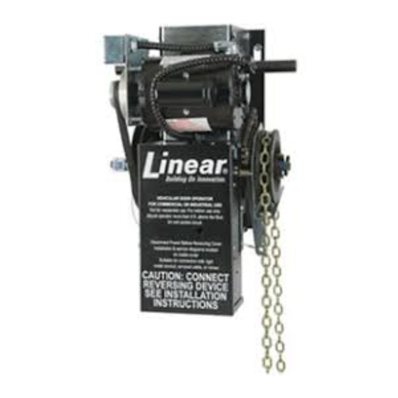
TABLE OF CONTENTS Product Features......................3 Jackshaft Operator Applications ................. 3 Preparation ........................4 Figure 1 - Component Identification Pictorial ............. 4 Important Installation Warnings (Things To Do Before & During Installation) ..5 Table 1 - Component Identification Listing ..............5 Installation Instructions ................... -
Page 3: Product Features
Radio units are available to control up to 27 doors from one For the ultimate in protection, terminals are provided to connect a transmitter Linear Corp. Photo-Beam System that consists of an emitter, Part Keyless Entry System: Connection terminals provided for No. 217792 and detector, Part No. 217800. This device when hard wired or wireless keyless entry systems. -
Page 4: Preparation
PREPARATION verify that it is the correct model for the intended application WARNING and that the voltage and phase are in accordance with electrical power provided at the job site. If the operator was ordered with the optional chain hoist, Model H-S, see that it is ELECTRIC DOOR OPENERS ARE DESIGNED so equipped. -
Page 5: Important Installation Warnings (Things To Do Before & During Installation)
IMPORTANT INSTALLATION INSTRUCTIONS! TO REDUCE THE RISK OF SEVERE WARNING INJURY OR DEATH: READ AND FOLLOW ALL INSTALLATION INSTRUCTIONS! • Install only on a properly operating and balanced • Install the door operator at least 8 feet or more garage door. A door that is operating improperly above the floor if the operator has exposed could cause severe injury. - Page 6 INSTALLATION INSTRUCTIONS SPRINGS, PULLEYS, CABLES AND MOUNTING HARDWARE USED TO BALANCE YOUR GARAGE DOOR ARE UNDER EXTREME TENSION AT ALL TIMES AND CAN CAUSE SEVERE INJURY OR DEATH IF DISTURBED. WARNING DO NOT ATTEMPT ADJUSTMENT. life of the bearings. If there is any flexibility in the system due igure 6, page 8 illustrates several positions suitable for to construction of the surface supporting the operator or mounting the operator;...
- Page 7 INSTALLATION INSTRUCTIONS CHAIN HOIST AND FLOOR DISCONNECT INSTALLATION If the operator is furnished with a chain hoist (Model H-S), pass the hand chain over the chain wheel and through the chain guides on the operator clutch shaft (opposite end from the large pulley). Fasten the ends of the chain together by opening and re-closing one link using two pairs of pliers.
- Page 8 OPERATOR MOUNTING POSITIONS Center Right Side Left Side Mount Mount Mount Direct Ceiling Couple Mount Ceiling Mount Wall Mount Wall Mount Figure 6 100719...
- Page 9 OPERATOR DIMENSIONS - MODEL J-S & H-S 107841 Figure 7 - Dimensions Model H-S 108203 Figure 7A - Dimensions Model J-S...
-
Page 10: Setting The Limits
INSTALLATION INSTRUCTIONS Depress the limit nut retaining Plate (D) so it disengages WARNING from the slots in the limit nuts. Turn the OPEN limit nut (E) on the shaft until it engages the Open Limit Switch (A). You will TO AVOID RISK OF ENTRAPMENT AND need to listen for an audible click. -
Page 11: Installation Instructions
Refer to the instructions on Page 12 for the Connect the appropriate voltage and phase power leads to the Linear photoelectric system installation and wiring. appropriate terminals as per the wiring diagram and connect a If the external entrapment protection device is connected, the ground wire to the grounding screw. -
Page 12: Safety Beam Photoelectric Entrapment Protection Device Installation
DOOR EDGE and PHOTOELECTRIC INSTALLATION Note: See the door edge manufacturer‟s installation instructions for the complete installation procedure. See Figure 9 for connecting the edge to the operator. See Page 16 for proper setting of the selector switches. These switches must be properly set and an approved photo- electric device or approved door edge device connected to the operator to obtain B2 Mode of Operation, Momentary Contact to Close. - Page 13 SAFE FINISH PHOTOBEAM OPEN CLOSE STOP MOTOR CONTROL Figure 9 BOARD 3-WIRE PHOTOBEAM Linear Approved 2 Wire Door Edge Photoelectric Detector Emitter Protection Device wiring. Note: This device can be used for Entrapment Part # Part # SAFE FINISH PHOTOBEAM...
-
Page 14: Figures 11-13 Field Wiring
3/SINGLE BUTTON STATION / INTERLOCK FIELD WIRING MOTOR RADIO MOTOR CONTROL CONTROL BOARD BOARD OPEN CLOSE STOP OPEN CLOSE STOP Single 3 Button Station Figure 11 Multiple 3 Button Station Figure 12 Figure 13 MOTOR CONTROL BOARD Single Button and External Interlock Wiring Note: When adding an External Interlock remove the factory installed jumper from the connection terminals. -
Page 15: Operation And Adjustment Instructions
OPERATION & ADJUSTMENT INSTRUCTIONS IMPORTANT SAFETY INSTRUCTIONS FOR OWNER TO REDUCE THE RISK OF SEVERE WARNING INJURY OR DEATH: READ AND FOLLOW ALL INSTRUCTIONS! Understand all of the operating features of your door control system at the time of its installation. Your installing dealer will demonstrate them for you. -
Page 16: Switch Selectable Operating Modes
OPERATION & ADJUSTMENT INSTRUCTIONS SETTING THE SWITCH SELECTABLE OPERATING MODES Changing the Switch Selectable Operation Modes Settable The following modes are selected by setting the on-board dip Switches switches, Figure 14 at right shows where the switches are Location located on the operator control board. For each Operational HIGH VOLTAGE Mode, the switches are set to either ON or OFF according to the table at right below. -
Page 17: Operating Characteristics Setup Modes
OPERATION & ADJUSTMENT INSTRUCTIONS Mid-Stop: Activation stops an opening door; momentary contact T Operation, Dip-Switch Setting of open button at mid stop will restart door to full open Open Button: Momentary activation; open override of closing position; if door is moving open, constant pressure on open door. -
Page 18: Brake Adjustment
OPERATION & ADJUSTMENT INSTRUCTIONS Mid-Stop Limit Setup setting the switches to the appropriate settings in the table, pressing STOP will clear and turn off the auto close timer. This features provides a timing function to stop a door as it is Every time OPEN is pressed, 5 seconds is added to the time. -
Page 19: Clutch Adjustment
OPERATION & ADJUSTMENT INSTRUCTIONS CLUTCH ADJUSTMENT REQUIRED TO THE DOOR, DOOR SPRINGS OR DOOR WARNING OPERATOR MUST BE PREFORMED BY A QUALIFIED PROFESSIONAL DOOR INSTALLER. RISK OF ENTRAPMENT THAT MAY RESULT The clutch pad will wear during normal operation and should be IN SERIOUS PERSONAL INJURY OR DEATH. -
Page 20: Safety Beam Photoelectric Entrapment Protection Device Adjustment
OPERATION & ADJUSTMENT INSTRUCTIONS... -
Page 21: Testing
OPERATION & ADJUSTMENT INSTRUCTIONS TESTING Following installation, the operator MUST be tested and respond correctly to all controls as specified on the wiring CAUTION diagram. KEEP personnel and equipment clear of the area DO NOT STAND UNDER DOOR beneath the door when performing the tests. When testing the 3 -button wall station, first observe that each button operates the TO TEST REVERSING FEATURE door in the direction indicated and that the STOP button... -
Page 22: Wiring Diagram - Single Phase
WIRING DIAGRAM/SCHEMATIC - SINGLE PHASE CLOSE LIMIT WHITE GREY GREY ORANGE ORANGE BLUE YELLOW OPEN LIMIT WHITE OVERLOAD DEVICE BLACK WHITE HIGH VOLTAGE OPERATING MODES GROUND SWITCH SETTINGS POWE MODE S1 S2 OFF OFF OFF OFF ON OFF OFF OFF OFF ON OFF OFF ON OFF OFF LINE... -
Page 23: Wiring Diagram - Three Phase
WIRING DIAGRAM/SCHEMATIC - THREE PHASE CLOSE LIMIT WHITE GREY GREY ORANGE ORANGE BLUE +CONNECTION SHOWN FOR 208 & 230V - FOR 460V SEE MOTOR DIAG. OPEN LIMIT ON INSIDE OF CONT. BOX COVER OVERLOAD DEVICE ORANGE BLACK WHITE HIGH VOLTAGE OPERATING MODES GROUND SWITCH SETTINGS... - Page 24 NOTES...
-
Page 25: Parts Identification
PARTS IDENTIFICATION Description Part# Parts Description 009221 Shaft Collar, 1” Part# 008071 Flange Bearing, 3/4” Assemblies 100487 Flange Bearing, 1” 105933 Frame Assembly w/Shafts. J 105549 Snap Ring, 3/4” 109318 Frame Assembly w/Shafts, H 105550 Snap Ring, 1” 106501 Drive Shaft Assembly, J/H 100315 Hand Chain, AUH 105930 Disconnect Shaft Assembly, J 105251 Sprocket, 41B12, 1”... -
Page 26: Operator Specifications
There are no obligations or liabilities on the part of Linear LLC for consequential damages arising out of or in connection with use or performance of this product or other indirect damages with respect to loss of property, revenue, or profit, or cost of removal, installation, or reinstallation.
Need help?
Do you have a question about the J Series and is the answer not in the manual?
Questions and answers