Table of Contents
Advertisement
Quick Links
INM725B
725B Series ALARM ANNUNCIATOR
INSTRUCTION MANUAL
REV
DATED
DESCRIPTION
17
06-12-11
Added Additional functionality
18
12-01-12
Added Enhanced Comms Option
19
25-05-12
Added more detail on IEC61850
20
16-09-13
Advice on lifting and external PSU type
21
13-10-14
Update to safe operating instructions
725B Instruction Manual – Rev 21
AUTHOR
APPROVED
D.Adams
P.Cartmell
D.Adams
P.Cartmell
D.Adams
P.Cartmell
A Ibbetson
P.Cartmell
J. Cooke
D. Fishkin
Page 1 of 124
Advertisement
Table of Contents

Related Manuals for RTK 725B Series


Summary of Contents for RTK 725B Series
- Page 1 INM725B 725B Instruction Manual – Rev 21 725B Series ALARM ANNUNCIATOR INSTRUCTION MANUAL DATED DESCRIPTION AUTHOR APPROVED 06-12-11 Added Additional functionality D.Adams P.Cartmell 12-01-12 Added Enhanced Comms Option D.Adams P.Cartmell 25-05-12 Added more detail on IEC61850 D.Adams P.Cartmell 16-09-13 Advice on lifting and external PSU type A Ibbetson P.Cartmell...
-
Page 2: Table Of Contents
INM725B 725B Instruction Manual – Rev 21 SECTION 1 - INTRODUCTION ..............6 General ........................... 6 Programmable Features ....................6 Glossary of Terms ......................7 Annunciator Model Code Definition ................. 8 Product Overview ......................10 ... - Page 3 INM725B 725B Instruction Manual – Rev 21 Setting Inputs for use with 48VDC ................. 54 Setting Inputs for use with 48VAC ................. 54 Standard 24VDC Signal Input Wiring ................55 Optional 24VDC Powered Input Wiring ................56 ...
- Page 4 Modbus Slave – Entry Level ..................96 Modbus Slave – Standard Communications ..............99 Modbus Master – Standard Communications .............. 109 RTK AMS ........................111 Wharton Format ......................111 Mapping ........................112 IEC61850 Server ......................118 ...
- Page 5 INM725B 725B Instruction Manual – Rev 21 The following methods are used in this manual to alert the user to important information:- WARNING! Warnings are provided for safety and MUST be followed CAUTION Cautions are provided to prevent damage to the instrument. NOTE These are used to give general information to ensure correct operation.
-
Page 6: Section 1 - Introduction
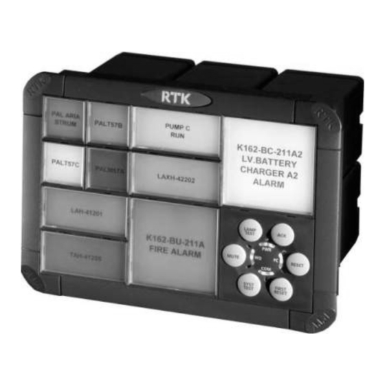
SECTION 1 - INTRODUCTION General The RTK 725B Series alarm annunciator is used to inform the operator that a process has gone beyond set limits using visual and audible alarms. The Annunciator is manufactured from universal cells which can be assembled in an array to provide the number of rows and columns required to suit individual panel designs. -
Page 7: Glossary Of Terms
INM725B 725B Instruction Manual – Rev 21 Glossary of Terms Cell: A single module 60mm x 60mm which can be joined to adjacent cells in varying heights and widths to provide the number of alarms required. The number of alarms available per Cell depends on the window size required. -
Page 8: Annunciator Model Code Definition
INM725B 725B Instruction Manual – Rev 21 Annunciator Model Code Definition Code Description Model No Series 725B Window Size Small – 30 mm w x 30mm h Medium – 60mm w x 30mm h Large – 60mm w x 60mm h Intermixed –... - Page 9 Entry Level – Addressing each alarm card individually Standard – RS485 and Ethernet (SNTP only) Enhanced – RS485, Ethernet, Additional Ethernet Port Protocol Options Not Fitted RTK AMS (Entry Level), Serial Modbus and AMS(Standard) Serial Modbus RTU (Entry Level) DNP3 Unarmed (Enhanced) IEC61850 Unarmed (Enhanced) IEC61850 (Enhanced)
-
Page 10: Product Overview
INM725B 725B Instruction Manual – Rev 21 Product Overview The 725B is a modular alarm annunciator constructed from 60mm x 60mm cells to form a single unit suitable for mounting in a panel cut-out. This modular design allows units to be constructed in vast range of heights and widths to suit individual panel designs and allows systems to be supplied from a single alarm to a maximum of 256 alarms per annunciator. -
Page 11: Window Illumination
INM725B 725B Instruction Manual – Rev 21 Number Of Alarms Per Cell Each 60mm x 60mm cell within the annunciator can contain 1, 2 or 4 alarms depending on the required window size:- Window Style Window Size (W x H) Alarms per Cell Large 60mm x 60mm... - Page 12 INM725B 725B Instruction Manual – Rev 21 Please note the CB7028POP1 white LED assembly is factory fitted with the half circle in the top left hand corner as shown above. If the LED assembly is inserted while power is applied to the system the LED may blink when it is first inserted but will automatically return to the off state if no alarm is present.
-
Page 13: Window Colours
INM725B 725B Instruction Manual – Rev 21 Window Colours Each channel is equipped with its own removable lens assembly, which, contains a coloured filter and a laser printed film legend. White filters are used in standard applications but coloured filters can be used as an alternative to provide a clear indication of alarm type. -
Page 14: Filter & Bezel Spare Parts Numbers
Window Numbering System RTK have adopted the following window numbering system to aid with the location of the film legend and the associated alarm cards. This method is used to ensure that the legend matches the functions selected for the designated alarm. -
Page 15: Integral Pushbutton Module
INM725B 725B Instruction Manual – Rev 21 Integral Pushbutton Module On standard systems the pushbutton / programming module is located in the bottom right hand corner of the annunciator when viewed from the front. If advised at time of order the pushbutton module can be located in any alternative cell within the annunciator. -
Page 16: Usb Programming Port
INM725B 725B Instruction Manual – Rev 21 USB Programming port WARNING! Installation, configuration and maintenance of this annunciator must only be performed by competent service personnel WARNING! Hazardous voltages may be present when pushbutton panel is removed. Take care not to touch any exposed parts on pushbutton panel or annunciator beyond those specified in the instructions below. -
Page 17: Cal Mode
INM725B 725B Instruction Manual – Rev 21 CAL Mode WARNING! Installation, configuration and maintenance of this annunciator must only be performed by competent service personnel WARNING! Hazardous voltages may be present when pushbutton panel is removed. Take care not to touch any exposed parts on pushbutton panel or annunciator beyond those specified in the instructions below. -
Page 18: Signal Input Contact Status
INM725B 725B Instruction Manual – Rev 21 Signal Input Contact Status During commissioning or fault finding the user can easily determine the current status of all of the plant inputs connected to the alarm annunciator by placing the unit into CAL mode. Once in this mode each window on the 725B indicates the dynamic status of the associated plant input. - Page 19 INM725B 725B Instruction Manual – Rev 21 Channel Up Function Up Channel Down Function Down Function Up / Down The integral pushbutton module has two functions. 1. It can be used to dynamically view the status of all signal inputs to determine which inputs are open or closed.
-
Page 20: Remote Pushbutton Module
INM725B 725B Instruction Manual – Rev 21 Remote Pushbutton Module As an alternative the 725B can be fully equipped with alarm windows and the Pushbutton Module can be supplied as a remote item or the user can use conventional panel mounting momentary, N/O, pushbuttons to control the annunciator. -
Page 21: Section 2 - Cell Types
INM725B 725B Instruction Manual – Rev 21 SECTION 2 – CELL TYPES Each 725B alarm annunciator is constructed from modular building blocks, “CELLS”. The type of card installed within each cell is dependent on the options required. WARNING! Hazardous voltages may be present on the rear panel connections when module connectors are removed. -
Page 22: A Cell - Differential Input Version
INM725B 725B Instruction Manual – Rev 21 A Cell - Differential Input Version Cell type A is used to provide:- Four isolated digital inputs for use with volt-free or powered contacts The drawing above indicates the OPTIONAL differential input version where each channel is provided with a fully isolated bi-polar input. -
Page 23: Ar Cell Detail
INM725B 725B Instruction Manual – Rev 21 AR Cell Detail (Alarm – Relay Cell) Cell type AR is used to provide:- Four digital inputs for use with volt-free or powered contacts Four repeat relays providing volt-free contact outputs for use with third party devices ... -
Page 24: Ar Cell - Differential Input Version
INM725B 725B Instruction Manual – Rev 21 AR Cell - Differential Input Version CELL 1 - REAR VIEW RELAY CARD VERSION USED IN "AR" CELLS (UPPER SLOT) RELAY OUTPUTS CB6613POP1 (4) CHANNEL RELAY CARD ALARM CARD VERSIONS USED IN "AR" CELLS 5 - 8 (LOWER SLOT) CHANNEL... -
Page 25: Ap Cell Detail
INM725B 725B Instruction Manual – Rev 21 AP Cell Detail (Alarm – Pushbutton Cell) Cell type AP is used to provide:- Four digital inputs for use with volt-free or powered contacts Three external pushbutton inputs for use with optional remote mounting pushbuttons as required. -
Page 26: Apr Cell Detail
INM725B 725B Instruction Manual – Rev 21 APR Cell Detail (Alarm / Pushbutton – Relay Cell) Cell type APR is used to provide:- Four digital inputs for use with volt-free or powered contacts Three external pushbutton inputs for use with optional remote mounting pushbuttons as required. -
Page 27: Ap6 Cell Detail
INM725B 725B Instruction Manual – Rev 21 AP6 Cell Detail (Alarm Card - Remote Pushbutton) REAR VIEW REMOTE PB CARD VERSIONS USED IN "AP6" CELLS PUSHBUTTONS (UPPER SLOT) CB9427POP1 – REMOTE PUSHBUTTON CARD ALARM CARD VERSIONS USED IN "AP6" CELLS (LOWER SLOT) CHANNEL INPUTS... -
Page 28: Awr Cell Detail
INM725B 725B Instruction Manual – Rev 21 AWR Cell Detail (Alarm – Watchdog Relay Cell) Cell type AWR* is used to provide:- Four digital inputs for use with volt-free or powered contacts Four Common Relays which can be programmed for use as horn, common alarm or diagnostic watchdog relays ... -
Page 29: As Cell Detail
INM725B 725B Instruction Manual – Rev 21 AS Cell Detail (Alarm – Supply Cell) Cell type AS is used to provide:- Four digital inputs for use with volt-free or powered contacts Universal Input Power Supply capable of accepting either:- ... -
Page 30: As Cell - Differential Input Version
INM725B 725B Instruction Manual – Rev 21 AS Cell - Differential Input Version Cell type AS is used to provide:- Four Isolated digital inputs for use with volt-free or powered contacts Universal Input Power Supply capable of accepting either:- ... -
Page 31: S Cell Detail
INM725B 725B Instruction Manual – Rev 21 S Cell Detail (Supply Cell) Cell type S is used to provide:- Universal Input Power Supply capable of accepting either:- AC voltages in the range 85-264VAC or DC voltages in the range 88-300VDC ... -
Page 32: Ss Cell Detail
INM725B 725B Instruction Manual – Rev 21 SS Cell Detail (Supply - Supply Cell) Cell type SS is used to provide:- Dual Universal Input Power Supply each capable of accepting either AC voltages in the range 85-264VAC or ... -
Page 33: Wr Cell Detail
INM725B 725B Instruction Manual – Rev 21 WR Cell Detail (Watchdog - Relay Cell) REAR VIEW RELAY CARD VERSION USED IN "WR" CELLS (LOWER SLOT) CB6641POP1 - WATCHDOG / RELAY CARD RELAY OUTPUTS Cell type WR is used to provide:- WR cells are equipped with a four channel relay card which provide ... -
Page 34: Wrs Cell Detail
INM725B 725B Instruction Manual – Rev 21 WRS Cell Detail (Watchdog / Relay - Supply Cell) Cell type WRS is used to provide:- WR cells are equipped with a four channel relay card which provide Four Common Relays which can be programmed for use as horn, common alarm or watchdog relays ... -
Page 35: Wrr Cell Detail
INM725B 725B Instruction Manual – Rev 21 WRR Cell Detail (Watchdog / Relay - Relay Cell) REAR VIEW RELAY CARD VERSION USED IN "WRR" CELLS RELAY OUTPUTS (UPPER SLOT) CB6613POP1 - (4) CHANNEL RELAY CARD RELAY CARD VERSION USED IN "WRR" CELLS (LOWER SLOT) CB6641POP1 - WATCHDOG / RELAY CARD RELAY OUTPUTS... -
Page 36: Optional Wr Cell Detail
INM725B 725B Instruction Manual – Rev 21 Optional WR Cell Detail (Watchdog - Relay Cell) used on systems not equipped with integral Pushbutton / Programming Modules REAR VIEW RELAY CARD VERSION USED IN "WR" CELLS (LOWER SLOT) CB6641POP2 - WATCHDOG / RELAY CARD FOR USE WITH SYSTEMS NOT EQUIPPED WITH INTEGARL PUSHBUTTONS RELAY OUTPUTS... - Page 37 INM725B 725B Instruction Manual – Rev 21 Four Common Relays which can be programmed for use as horn, common alarm or diagnostic watchdog relays Each of the output contacts can be set to N/C or N/O using a 3 way header and 2 way shorting bar located on the card.
-
Page 38: Wrp Cell Detail
INM725B 725B Instruction Manual – Rev 21 WRP Cell Detail (Watchdog Relay Card - Remote Pushbutton) REAR VIEW REMOTE PB CARD VERSIONS USED IN "WRP" CELLS PUSHBUTTONS (UPPER SLOT) CB9427POP1 – REMOTE PUSHBUTTON CARD RELAY CARD VERSION USED IN "WRP" CELLS (LOWER SLOT) CB6641POP1 - WATCHDOG / RELAY CARD COMMON RELAYS... -
Page 39: Ac Cell Detail
INM725B 725B Instruction Manual – Rev 21 AC Cell Detail (Alarm – Comms Cell) Cell type AC is used to provide:- Four digital inputs for use with volt-free or powered contacts. Comm’s Card that provides: One isolated RS485 Port via a standard 9-way D-type connector. ... -
Page 40: Apc Cell Detail
INM725B 725B Instruction Manual – Rev 21 APC Cell Detail (Alarm – Pushbutton - Comm’s Cell) Cell type APC is used to provide:- Four digital inputs for use with volt-free or powered contacts Three external pushbutton inputs for use with optional remote mounting pushbuttons as required. -
Page 41: C Cell Detail
INM725B 725B Instruction Manual – Rev 21 C Cell Detail (Comm’s Cell) REAR VIEW COMMS CARD VERSION USED IN "C" CELLS PORT 2 PORT 4 (UPPER SLOT) CB7515POP1 - COMMS CARD Cell type C is used to provide:- Comm’s Card that provides: ... -
Page 42: Wrc Cell Detail
INM725B 725B Instruction Manual – Rev 21 WRC Cell Detail (Watchdog / Relay - Comm’s Cell) REAR VIEW COMMS CARD VERSION USED IN "WRC" CELLS PORT 2 PORT 4 (UPPER SLOT) CB7515POP1 - COMMS CARD RELAY CARD VERSION USED IN "WRC" CELLS (LOWER SLOT) CB6641POP1 - WATCHDOG / RELAY CARD RELAY OUTPUTS... - Page 43 INM725B 725B Instruction Manual – Rev 21 CE Cell Detail (Comms Enhanced Cell) REAR VIEW COMMS CARD VERSION USED IN "CE" CELLS PORT 3 (UPPER SLOT) CB10257POP1 - ENHANCED COMMS CARD WITH IEC61850 CB10257POP2 - ENHANCED COMMS CARD WITH DNP3 Cell type CE is used to provide:- Enhanced Comm’s Card that provides: ...
-
Page 44: Ace Cell Detail
INM725B 725B Instruction Manual – Rev 21 ACE Cell Detail (Alarm – Comm’s Enhanced Cell) REAR VIEW COMMS CARD VERSION USED IN "ACE" CELLS (UPPER SLOT) PORT 3 CB10257POP1 - ENHANCED COMMS CARD WITH IEC61850 CB10257POP2 - ENHANCED COMMS CARD WITH DNP3 ALARM CARD VERSIONS USED IN "ACE"... -
Page 45: Wrce Cell Detail
INM725B 725B Instruction Manual – Rev 21 WRCE Cell Detail (Watchdog / Relay - Comm’s Enhanced Cell) REAR VIEW COMMS CARD VERSION USED IN "WRCE" CELLS PORT 3 (UPPER SLOT) CB10257POP1 - ENHANCED COMMS CARD WITH IEC61850 CB10257POP2 - ENHANCED COMMS CARD WITH DNP3 RELAY CARD VERSION USED IN "WRCE"... -
Page 46: Cec Cell Detail
INM725B 725B Instruction Manual – Rev 21 CEC Cell Detail (Comm’s Enhanced – Comm’s Cell) REAR VIEW COMMS CARD VERSION USED IN "CEC" CELLS PORT 2 PORT 4 (UPPER SLOT) CB7515POP1 - COMMS CARD ENHANCED COMMS CARD VERSION USED IN "CEC" CELLS (LOWER SLOT) CB10257POP1 –... -
Page 47: Pce Cell Detail
INM725B 725B Instruction Manual – Rev 21 PCE Cell Detail (Remote Pushbutton - Comm’s Cell) REAR VIEW COMMS CARD VERSION USED IN "PCE" CELLS PORT 3 (UPPER SLOT) CB10257POP1 - ENHANCED COMMS CARD WITH IEC61850 CB10257POP2 - ENHANCED COMMS CARD WITH DNP3 PUSHBUTTONS ALARM CARD VERSIONS USED IN "PCE"... -
Page 48: Usb Programming Port Location
INM725B 725B Instruction Manual – Rev 21 USB Programming Port Location The USB port has TX and RX Status LED’s to monitor communication activity. RELAY CARD VERSION USED IN "WR" CELLS REAR VIEW (LOWER SLOT) CB6641POP2 - WATCHDOG / RELAY CARD FOR USE WITH SYSTEMS NOT EQUIPPED WITH INTEGARL PUSHBUTTONS RELAY OUTPUTS... -
Page 49: Section 3 - Logic Supply & Fusing
INM725B 725B Instruction Manual – Rev 21 SECTION 3 – LOGIC SUPPLY & FUSING All 725B Alarm Annunciators operate from a 24VDC logic supply. Any external power supply connected to the annunciator must be compliant to UL60950 or EN60950 or suitable equivalent standards. Externally Powered Systems When external power supplies are used 24VDC must be connected to terminals OV and +V as shown below. -
Page 50: Systems Using Internal Power Cards
INM725B 725B Instruction Manual – Rev 21 Systems using Internal Power Cards When internal power supply cards are used the logic voltage is internally connected and +V is used to provide a 1A 24VDC output for use as a signal supply voltage. -
Page 51: Section 4 - Power Supply Monitoring
INM725B 725B Instruction Manual – Rev 21 SECTION 4 – POWER SUPPLY MONITORING Power Monitor Relays On units with integral PSUs each annunciator can be equipped with two integral power monitor relays which provide volt-free contacts for use with 3 party devices to indicate loss of primary or aux supplies. -
Page 52: Setting Inputs For Use With 24Vdc Or 125Vdc
INM725B 725B Instruction Manual – Rev 21 SECTION 5 - SIGNAL VOLTAGE SETTING / WIRING Setting Inputs for use with 24VDC or 125VDC On standard 725B systems each 4 channel alarm card is suitable for use with 24VDC or 125VDC signal inputs. Each channel on the alarm card is equipped with a 3 pin header and 2 way shorting bar that allows the user to set the input to match the required signal input voltage level. - Page 53 INM725B 725B Instruction Manual – Rev 21 CHANNEL 1 SIGNAL SUPPLY VOLTAGE SETTING CHANNEL 2 CHANNEL 1 CHANNEL 3 SIGNAL SUPPLY CHANNEL 4 SET TO 24V 125V 125V SIGNAL SUPPLY SET TO 125V 125V The settings are available on the following (4) channel alarm cards Card Type Features CB6611POP1...
-
Page 54: Setting Inputs For Use With 48Vdc
INM725B 725B Instruction Manual – Rev 21 Setting Inputs for use with 48VDC As an option 725B systems can be supplied with each 4 channel alarm card suitable for use with 48VDC signal inputs. Setting Inputs for use with 48VAC 725B signal inputs are bi-polar and therefore suitable for use with 48VAC. -
Page 55: Standard 24Vdc Signal Input Wiring
INM725B 725B Instruction Manual – Rev 21 Standard 24VDC Signal Input Wiring P1 P2 P3 - P4 P5 P6 5 - 8 1 - 4 CHANNEL CHANNEL INPUTS INPUTS 1C 2C 2C 3C 4C OV OV OVC +VC 24VDC SIGNAL SUPPLY LINKED FROM THE LOGIC SUPPLY Each channel on the alarm card is provided with a 3 pin header and 2 way... -
Page 56: Optional 24Vdc Powered Input Wiring
INM725B 725B Instruction Manual – Rev 21 Optional 24VDC Powered Input Wiring 725B SMALL WINDOW VERSION TYPICAL REAR VIEW CELL 2 CELL 1 CELL 0 5 - 8 1 - 4 CHANNEL CHANNEL INPUTS INPUTS 1C 2C 2C 3C OV OV OVC +VC +24VDC POWERED INPUTS +24VDC POWERED INPUTS... -
Page 57: Optional 24Vac Signal Input Wiring
INM725B 725B Instruction Manual – Rev 21 Optional 24VAC Signal Input Wiring 725B SMALL WINDOW VERSION TYPICAL REAR VIEW CELL 2 CELL 1 CELL 0 F2 - 1A INTERNAL SIGNAL SUPPLY COMMON 5 - 8 1 - 4 CHANNEL CHANNEL INPUTS INPUTS 1C 2C... - Page 58 INM725B 725B Instruction Manual – Rev 21 Optional 125VDC Signal Input Wiring P1 P2 P3 P4 P5 P6 5 - 8 1 - 4 CHANNEL CHANNEL INPUTS INPUTS 1C 2C 2C 3C 4C OV OV OVC +VC 125VDC SIGNAL SUPPLY Each channel on the alarm card is provided with a 3 pin header and 2 way shorting bar which allows the user to select the inputs to operate on 125V.
-
Page 59: Optional 125Vac Signal Input Wiring
INM725B 725B Instruction Manual – Rev 21 Optional 125VAC Signal Input Wiring 725B SMALL WINDOW VERSION TYPICAL REAR VIEW CELL 2 CELL 1 CELL 0 INTERNAL SIGNAL F2 - 1A SUPPLY COMMON 5 - 8 1 - 4 CHANNEL CHANNEL INPUTS EXT PB INPUTS... -
Page 60: Optional 48Vdc Signal Input Wiring
OVC +VC 48VDC SIGNAL SUPPLY VOLTAGE Note:- In applications that require 48VDC signal inputs RTK supply optional 4 channel alarm cards in place of the standard version 48VDC Signal Supply On 725B systems where 48VDC is required as a signal supply voltage this needs to be derived externally and connected to terminals OVC and +VC as typically shown above. -
Page 61: Optional 48Vac Signal Input Wiring
OVC +VC 48VAC SIGNAL SUPPLY VOLTAGE Note:- In applications that require 48VAC signal inputs RTK supply optional 4 channel alarm cards in place of the standard version 48VAC Signal Supply On 725B systems where 48VAC is required as a signal supply voltage this needs to be derived externally and connected to terminals OVC and +VC as typically shown above. -
Page 62: Optional Differential Input Version Wiring
725B Instruction Manual – Rev 21 Optional Differential Input Version Wiring As an option RTK can supply fully isolated inputs for each alarm way. As the Inputs are bi-polar the user can switch AC or DC voltages as required. 725B SMALL WINDOW VERSION TYPICAL REAR VIEW... -
Page 63: Section 6 - Common Relays
INM725B 725B Instruction Manual – Rev 21 SECTION 6 – COMMON RELAYS REAR VIEW RELAY CARD VERSION USED IN "WR" CELLS (LOWER SLOT) CB6641POP1 - WATCHDOG / RELAY CARD RELAY OUTPUTS Four common relays are located in the WR Cell within the Annunciator as shown above. -
Page 64: Group Relay
INM725B 725B Instruction Manual – Rev 21 RELAY CONTACT STATE NORMALLY CLOSED CARD ADDRESS DIL SWITCH SW1 NORMALLY OPEN The coil state of each relay can be set to EN or DE-EN as described in the software configuration section of this manual. Multiple common relay cards may be present in larger systems to provide the necessary features. -
Page 65: Group Relay With Reflash
INM725B 725B Instruction Manual – Rev 21 Group Relay with Reflash A common relay can be set to reflash each time a new event occurs within the group to prevent subsequent events being masked by a standing alarm Pushbutton Follower Relay Any common relay can be set to follow the action of any pushbutton. -
Page 66: Ground Fault Monitoring
INM725B 725B Instruction Manual – Rev 21 Ground Fault Monitoring If the optional ground fault monitoring card is fitted the common relay will change state whenever a ground fault is detected and will remain in the abnormal state until the ground fault has been cleared. LED Failure Monitoring If any window suffers a total failure of the LED assemblies the common relay will change state and will remain in the abnormal state until illumination is... -
Page 67: Section 7- Individual Channel Repeat Relays
INM725B 725B Instruction Manual – Rev 21 SECTION 7– INDIVIDUAL CHANNEL REPEAT RELAYS Each four channel alarm card can be supplied with an optional four channel relay card, part no CB6613POP1, which plugs into the four channel alarm card and provides the user with a volt-free contact per alarm channel for use with 3 Party devices. -
Page 68: Display Follower
INM725B 725B Instruction Manual – Rev 21 Display Follower The relay changes state on alarm and faithfully follows the display window i.e. Flashing, Steady or Off depending on the alarm sequence selected for this channel. Cancel System Test Relay On systems supplied after February 1 2010 using configuration software version 2.0.5 or higher the user is able to prevent the individual channel repeat relays operating when the system test pushbutton is pressed. -
Page 69: Section 8 - Typical 725B Rear Views
INM725B 725B Instruction Manual – Rev 21 SECTION 8 - TYPICAL 725B REAR VIEWS The following details are provided as typical examples of 725B Annunciator rear views showing alarm inputs, remote pushbutton inputs, common alarm relay outputs, 24VDC logic and signal wiring Typical Large Window Version, (each alarm window = 60mm w x 60mm h) CELL 6... -
Page 70: Typical Medium Window Version
INM725B 725B Instruction Manual – Rev 21 In large window versions of the 725B only the first cell in a group of four is supplied with an alarm card and the outputs are distributed to the next three cells – working down in columns then moving onto the next row. Typical Medium Window Version, (each alarm window = 60mm w x 30mm h), CELL 6... -
Page 71: Typical Small Window Version
INM725B 725B Instruction Manual – Rev 21 Typical Small Window Version, (each alarm window = 30mm w x 30mm h), INTERNAL SIGNAL SUPPLY COMMON CELL 6 CELL 4 CELL 2 CELL 0 25 - 28 17 - 20 9 - 12 1 - 4 CHANNEL CHANNEL... -
Page 72: Section 9 - Installation
If any damage has occurred please report the damage to the freight forwarder and copy RTK. The alarm annunciator is supplied with panel mounting clamps locked in place, however please check all packages to ensure that no additional pieces are left in the box as any auxiliary items like power supplies, horns, pushbuttons or spares kits will be packed separately. -
Page 73: Panel Mounting
INM725B 725B Instruction Manual – Rev 21 Panel Mounting WARNING! This annunciator is designed for panel mounting. The rear portion of the annunciator must be protected by an enclosure that is at least IP30 and can only be accessed using a key or tool. Access to the rear enclosure must be limited to service personnel only. -
Page 74: 19" Rack Mounting
The number of cells high is dependent on the available space available within the 19” rack. Wall Mounting RTK offer a full integration service where Panel mounted Annunciators are supplied within an industry standard Wall mounting Enclosure, with all customer connections typically wired to Weidmuller terminals for ease of connection to the field device. -
Page 75: Section 10- Specifications
In larger systems multiple integral power supplies can be used 3. Remote power supplies RTK offer a complete range of remote mounting AC/DC OR DC/DC power supplies in various wattages to suit individual applications and separate data sheets are available for these units. -
Page 76: Environmental Specifications
INM725B 725B Instruction Manual – Rev 21 First-Up discrimination Better than 10mS Outputs Individual channel repeat relays As an option each channel within the Annunciator can be supplied with a dedicated repeat relay with SPDT contacts allowing the user to jumper select a N/C or N/O contact for use with 3 Party devices. -
Page 77: Radiated Rfi Immunity
INM725B 725B Instruction Manual – Rev 21 Protection Annunciator front: IP41 Annunciator rear: IP20 Optional covers and Enclosures available for IP54 up to IP67 Radiated RFI Immunity IEC 61000-4-3 Conducted RFI Immunity IEC 61000-4-6 Radiated Emissions IEC 61000-6-3 Conducted Emissions IEC 61000-6-3 Radiated Power Frequency Magnetic Field IEC 61000-4-8... -
Page 78: Section 11 - Spare Parts List
INM725B 725B Instruction Manual – Rev 21 SECTION 11 - SPARE PARTS LIST Four Channel Alarm Cards 24V / 125V Signal Input Versions Part No Description CB6611POP1 Standard alarm card CB6611POP3 Alarm card plus three remote pushbutton inputs CB6611POP5 Alarm card plus sequential event recorder memory CB6611POP7 Alarm card with three remote pushbutton inputs and sequential event recorder memory... -
Page 79: White Led Assembly
INM725B 725B Instruction Manual – Rev 21 Remote Pushbutton Card Part No Description CB9427POP1 Remote Pushbutton Card SMR Card Part No Description CB9413POP1 SMR Card White LED Assembly Part No Description CB7028POP1 “Fit & Forget” White LED Assembly Integral Power Supply Part No Description CB6617POP1... -
Page 80: Usb Programming Cable
INM725B 725B Instruction Manual – Rev 21 Communication Card Part No Description CB7515POP1 Standard Communication Card CB10257POP1 Enhanced Comm’s Card with IEC61850 USB Programming Cable Part No Description 725B-USB USB Programming Cable Bezels Part No Description ML-7227-L Bezel for use with 60mm x 60mm Large Windows ML-7227-M Bezel for use with 60mm x 30mm Medium Windows ML-7227-S... -
Page 81: Section 12- Servicing
INM725B 725B Instruction Manual – Rev 21 SECTION 12- SERVICING Module Removal WARNING! Installation, configuration and maintenance of this annunciator must only be performed by competent service personnel WARNING! The 725B & 725C systems described herein operate on a logic voltage of 24VDC and as standard 24VDC is used for the field contact supply voltage. -
Page 82: Connected Equipment
INM725B 725B Instruction Manual – Rev 21 2. Undo the locking screws on either side of the terminal block on the rear of the cell. 3. Unplug the terminal block, which can be removed with field wiring still attached. 4. The plastic rear cover can be removed using a flat blade screwdriver to release the locking tabs on either side of the cover. -
Page 83: Card Address Setting
INM725B 725B Instruction Manual – Rev 21 Card Address Setting Before each card is placed within the annunciator a unique address number is set using the switches located on DIL switch SW1 as shown on a typical alarm card in the diagram below. WARNING! Remove ALL power from the unit and fully remove the card before changing any switches... -
Page 84: Small Window Versions
INM725B 725B Instruction Manual – Rev 21 Small Window versions. In the example shown 7 x four channel alarm cards plus 1 x common relay card would be fitted in the cell positions indicated below: CELL 6 CELL 4 CELL 2 CELL 0 25 - 28 17 - 20... -
Page 85: Medium Window Versions
INM725B 725B Instruction Manual – Rev 21 Medium Window versions. In the example shown 4 x four channel alarm cards plus 1 x common relay card would be fitted in the cell positions indicated below: CELL 6 CELL 4 CELL 2 CELL 0 13 - 14 9 -12... -
Page 86: Large Window Versions
INM725B 725B Instruction Manual – Rev 21 Large Window versions. In the example shown 2 x four channel alarm cards plus 1 x common relay card would be fitted in the cell positions indicated below: CELL 6 CELL 4 CELL 2 CELL 0 9 -12 1 - 4... -
Page 87: Typical Alarm Card Dil Switch Sw1 Address Settings
INM725B 725B Instruction Manual – Rev 21 Typical Alarm Card DIL Switch SW1 Address Settings ADDRESS BINARY SW1-8 SW1-7 SW1-6 SW1-5 SW1-4 SW1-3 SW1-2 SW1-1 00000000 00000001 00000010 00000011 00000100 00000101 00000110 00000111 00001000 00001001 00001010 00001011 00001100 00001101 00001110 00001111 00010000 00010001... -
Page 88: Section 13 - Contact / Returns
INM725B 725B Instruction Manual – Rev 21 SECTION 13 – CONTACT / RETURNS Measurement Technology Limited Great Marlings Butterfield Luton LU2 8DL United Kingdom Telephone / Fax Number List Telephone: 0044 (0) 1582 723633 Fax: 0044 (0) 1582 422283 Procedures for Factory Repair and Return Warranty Should you require to return an annunciator, please contact MTL for details. -
Page 89: Section 14 - Communications Options
1, the second card address 2 etc. Protocols Modbus RTU - Modbus Function 01 and Modbus Function 15 only. RTK AMS NOTE: On 725B annunciators supplied with Entry Level Comm’s, after September 2009, Modbus will be order specific and will only be available on alarm cards using software version SO9158. -
Page 90: Standard Comms Version
Port-4 provides a standard 8P8C (RJ45) Ethernet connection Serial Ports 725B annunciators supplied with standard comms are provided with the following communications protocols via Port-1 and Port-2 RTK AMS Modbus RTU Modbus ASCII Wharton Time Sync... - Page 91 INM725B 725B Instruction Manual – Rev 21 Port 2 Connection Details An Industry standard 9-way male d-type connector is provided on the rear of the communication card which provides the following connections:- 1 2 3 1 – Sync+ 2 – RxA 3 –...
- Page 92 INM725B 725B Instruction Manual – Rev 21 Typical Connections 725B 2 WIRE 725B 4 WIRE Ethernet Ports 725B annunciators supplied with standard comm’s are provided with the following communications protocols via Port 4:- SNTP (Simple Network Time Protocol) Client Port 4 Connection Details Port 4 is an Ethernet port which allows connection to an Ethernet network via a standard 8P8C (RJ45) connection.
-
Page 93: Enhanced Comm's Version
INM725B 725B Instruction Manual – Rev 21 Enhanced Comm’s Version 725B annunciators supplied with Enhanced comm’s are provided with an additional Ethernet port with the following Protocols: IEC61850 Server Port 3 Connection Details Port 3 is an Ethernet port which allows connection to an Ethernet network via a standard 8P8C (RJ45) connection. -
Page 94: Protocols
INM725B 725B Instruction Manual – Rev 21 Protocols MODBUS The tables below show the standard message formats for data interchange, for both ASCII (standard comm’s version Only) and RTU protocols. ASCII tables Each character represents 7 bit binary data in ASCII format with the exception of the characters in brackets, which should be considered as one character. - Page 95 INM725B 725B Instruction Manual – Rev 21 Single Write Request/Response Master write request and slave write response, are the same. REGISTER ERROR START ADDRESS FUNCTION DATA STOP ADDRESS CHECK ASCII XXXX XXXX [CR] [LF] REGISTER ERROR START ADDRESS FUNCTION DATA STOP ADDRESS CHECK...
-
Page 96: Modbus Slave - Entry Level
INM725B 725B Instruction Manual – Rev 21 Modbus Slave – Entry Level Function Descriptions This section describes the process of reading from and writing data to a 725B slave annunciator Read Coil Status – Function 01 – Request Register Address This is used to address the “start”... - Page 97 INM725B 725B Instruction Manual – Rev 21 Write Multiple Coils – Function 15 - Request Register Address This is used to address the “start” channel (coil) to be written. The register addresses field contains the address of data within the 725B Slave.
- Page 98 INM725B 725B Instruction Manual – Rev 21 Write Multiple Coils – Function 15 – Response Register Address Number of coils that have been written Quantity This represents the number of coils (Inputs), the user wishes to be written Typical Example of Message Format – Entry Level Comm’s To write to all of the inputs available on the first alarm card in the system the user would need to send the following message REGISTER...
-
Page 99: Modbus Slave - Standard Communications
INM725B 725B Instruction Manual – Rev 21 Modbus Slave – Standard Communications Function Descriptions This section describes the process of reading from and writing data to a 725B slave annunciator Read Coil Status – Function 01 – Request Register Address This is used to address the “start”... - Page 100 INM725B 725B Instruction Manual – Rev 21 Typical Example of Message Format To read all of the inputs available on a 100 way annunciator with a node address of 5 using the following message format REGISTER No Of ERROR ADDRESS FUNCTION ADDRESS REGISTERS...
- Page 101 INM725B 725B Instruction Manual – Rev 21 Read Status – Function 03 – Request Register Address This is used to address the “start” channel to be read for example the first channel in the system “channel 1” would be register address 00 00 To read the port register value the port offset is used to define the start address.
- Page 102 INM725B 725B Instruction Manual – Rev 21 Read Status – Function 03 – Response Byte Count This represents the number of bytes sent Data This represents the status of the requested register Port Register This will the value last written in the register requested, included any masked bits that have been ignored.
- Page 103 INM725B 725B Instruction Manual – Rev 21 Typical Example of Message Format To read all of the inputs on a 28 way annunciator on node 9 the user would use the following message format REGISTER No Of ERROR ADDRESS FUNCTION ADDRESS REGISTERS CHECK...
- Page 104 INM725B 725B Instruction Manual – Rev 21 Write Single Register – Function 6 - Request Register Address This is used to address the “start” register to be written to the port. If the port register offset has been set then this would offset the default start register.
- Page 105 INM725B 725B Instruction Manual – Rev 21 Write Single Register – Function 6 – Response Register Address The address of the register that has been written. Data This represents the data that has been written to the register. Typical Example of Message Format To write the input abnormal on channel 1 on node 1 the user would use the following message format REGISTER...
- Page 106 INM725B 725B Instruction Manual – Rev 21 Write Multiple Coils – Function 15 - Request Register Address This register is used to address the first coil to be written. If the port register offset has been set then this would offset the default start register. To write the input status write to coils 0 -255 with coil 0 being channel 1 unless mapping has been enabled then this will be defined in the mapping spreadsheet.
- Page 107 INM725B 725B Instruction Manual – Rev 21 Write Multiple Registers – Function 16 - Request Register Address This is used to address the “start” register to be written. If the port register offset has been set then this would offset the default start register.
- Page 108 INM725B 725B Instruction Manual – Rev 21 Bit 3 Pushbutton Group 4 Bit 4 Pushbutton Group 5 Bit 5 Pushbutton Group 6 Bit 6 Pushbutton Group 7 Bit 7 Pushbutton Group 8 Write Multiple Registers – Function 16 – Response Register Address Number of coils that have been written Quantity...
-
Page 109: Modbus Master - Standard Communications
INM725B 725B Instruction Manual – Rev 21 Modbus Master – Standard Communications Function Descriptions This section describes the process of receiving messages from a 725B master annunciator Read Coil Status – Function 01 – Request Register Address This is used to address the “start” coil to be read from the slave device Number of Registers This represents the number of slave coils the P725B wishes to read. - Page 110 INM725B 725B Instruction Manual – Rev 21 Read Status – Function 03 – Request Register Address This is used to address the “start” register to be read from the slave device Number of Registers This represents the number of registers to be read from the salve device this can be up to 125 register at once.
-
Page 111: Rtk Ams
RTK AMS When used with the optional Indicium RTK Alarm Management System the user needs to set the protocol to RTK AMS Slave Protocol in the drop down menu for communication to be established between the 725B and the associated PC based Indicium software. -
Page 112: Mapping
INM725B 725B Instruction Manual – Rev 21 Mapping Mapping is configured using the mapping spreadsheet. The spreadsheet is used to map port data to channels and also to setup the Modbus master block requests. Global Settings The Global settings worksheet shows the global setting configured on the unit when the mapping has been exported. - Page 113 INM725B 725B Instruction Manual – Rev 21 Setting up master data blocks (Master protocol only) In columns A and B (Source) the slave device node address and register addresses can be entered. This can be one continuous block or if more than one slave device is used up to 16 devices can be set up.
- Page 114 INM725B 725B Instruction Manual – Rev 21 The example below shows 3 separate blocks with one block with gaps. First block has node address 1, start register 40001 and 8 registers Block has node address 2, start register 40001 and 8 registers block has node address 3, start address 40001 and 15 registers with registers 40005, 40006 and 400013 unused.
- Page 115 INM725B 725B Instruction Manual – Rev 21 One to one Mapping If one to one mapping is required the spreadsheet is still required to set-up the master node address, Start address and number of registers. The output can then be entered in channel order to configure the one to one mapping. Alternatively if the user sets mapped port to None in the mapping tab the unit will default to one to one on all ports.
- Page 116 INM725B 725B Instruction Manual – Rev 21 Many to one Mapping Many registers/coils can be mapped to the same channel on the annunciator. They will be OR’d together so the channel will show the OR’d sum of all the mapped sources. The Reflash sequence on the channel can be used to reflash the alarm window if any of the source data changes state.
- Page 117 INM725B 725B Instruction Manual – Rev 21 Slave Mapping The slave spreadsheet allow the Port register to be mapped to the required channel. This work in the same way as the Master but columns A and B show the P725B port register addresses. Mapping Limits On the P725B the number of mapped points is limited to 656, this only includes mapped points, one to one points are not included in the mapping...
-
Page 118: Iec61850 Server
Rep4 - reporting data and quality change of card_status dataset Rep5 - reporting data and quality change of alarm dataset NOTE: Event type must be enabled in RTK configuration software otherwise no data change will be reported Datasets ... - Page 119 For full details of the IEC61850 protocol implementation refer to the PICS, MICS, TICS and PIXIT provided with the device. IP address, subnet mask and gateway can be configured via the RTK configuration software. The following application notes are available: ...
-
Page 120: Sntp Client
INM725B 725B Instruction Manual – Rev 21 SNTP Client The SNTP client is available on Port 4 and can be used to synchronise the annunciator with network time. The IP address, of the Server that will provide the time to the device, can be configured via the configuration software. -
Page 121: Section 15- Standard Comms Card Detail
INM725B 725B Instruction Manual – Rev 21 SECTION 15– Standard Comms Card Detail REAR VIEW COMMS CARD VERSION USED IN "C" CELLS PORT 2 PORT 4 (UPPER SLOT) CB7515POP1 - COMMS CARD 2 ports are located in the C Cell within the Annunciator as shown above. Port 2 gives an isolated RS485 port with the following pin out: 1 –... -
Page 122: Real Time Clock
INM725B 725B Instruction Manual – Rev 21 PORT4 PORT2 RX TX BATTERY CONNECTION TERMINATING RESISTORS NOT CONNECTED BAT1 ECTED CARD ADDRESS DIL SWITCH SW1 Real Time Clock The comm’s card comes with a battery backed RTC which keeps running even if power is lost to the unit. The Battery also powers the SRAM which is used to store the buffers on power loss. -
Page 123: Section 16 - Enhanced Comms Card Details
INM725B 725B Instruction Manual – Rev 21 SECTION 16 – Enhanced Comms Card Details Enhanced comms provides an additional Ethernet port. REAR VIEW COMMS CARD VERSION USED IN "CE" CELLS PORT 3 (UPPER SLOT) CB10257POP1 - ENHANCED COMMS CARD Port 3 is an Ethernet port which allows connection to an Ethernet network via a standard 8P8C (RJ45) connection. - Page 124 INM725B 725B Instruction Manual – Rev 21 SAFETY The Standard Comms card and Enhanced Comms cards are equipped with a lithium coin-cell long life battery. This battery should be removed by suitably qualified personnel at the end of its life. If required the replacement model numbers are: Comms card CR 2032 Coin cell.
Need help?
Do you have a question about the 725B Series and is the answer not in the manual?
Questions and answers