Advertisement
USER'S OPERATING MANUAL FOR PID DIGITAL TEMPERATURE CONTROLLER
SPECIFICATIONS : -
1. DISPLAY TYPE
Model no.
Px-418e
Display height (PV)
0.39"
Display height (SV)
0.24"
STATUS LED'S
2. INPUT
Sensor inpu
Range
Sensor Type
Range
Fe-k(J) T/C
0 ~ 760 C
Cr-AL(K) T/C
-99 ~ 1300 C
Pt-100(RTD)
-100 ~ 450 C
Pt-100(RTD 0.1)
-20.0 ~ 100.0 C
Sampling Time
Resolution
CJC for TC
LWC for Pt-100
Digital Filter
3. RELAY OUTPUT
Contact type
Contact Rating
Life expectancy
Isolation
4. SSR DRIVE OUTPUT
Drive Capacity
Isolation
5. FUNCTION
Output 1
Control Action
Control Mode
6. ENVIRONMENTAL
Operating Range
Storage Humidity
7. POWER SUPPLY
Supply Voltage
Consumption
8. PHYSICAL
Housing
(Models: Px 418 / 718 )
e
Px-
418
(48x48)
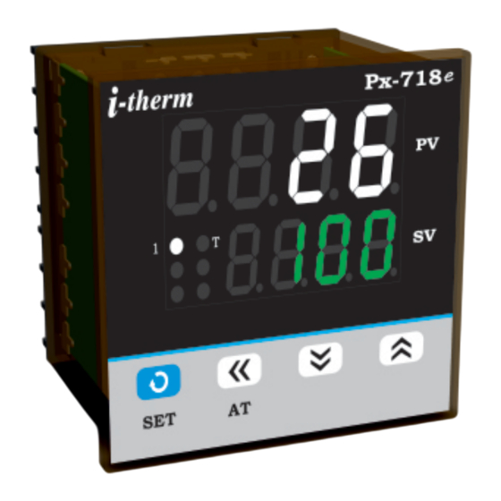
: Dual 4- Digit 7 segment LED
4 Digit Bright White (PV)
4 Digit Luminous Green (SV)
Px-718e Px-918e
0.70"
0.50"
: 1
: Control Output Status
T
: Tunning Stauts
i
: TC : J, K, RTD : Pt-100
: Refer below table.
Accuracy
Resolution
o
o
}
1 C
o
o
1 C
o
o
1 C
o
o
0.1 C
: 125 msec.
: 1°C
: Built in automatic
: Built in up to 18E max.
: 1 to 10 Sec.
: N/O, CM, N/C
: 5A @ 250VAC or 30 VDC
: > 5,00,000 operations
: Inherent
: 12V @ 30mA.
: Non-Isolated.
: Relay / SSR (Selectable)
: ON-OFF/PID (Selectable)
: Heat/Cool (Selectable)
: 0 ~50°C, 5~90% Rh
: 95% Rh (Non-condensing)
: 90~270VAC, 50/60Hz.
: 4W Maximum.
: ABS Plastic.
e
e
SAFETY INSTRUCTION :
This controller is meant for temperature control
applications. It is important to read the manual prior to
installing or commissioning of controller. All safety
related instruction appearing in this manual must be
followed to ensure safety of the operating personnel
as well as the instrument.
GENERAL
v The controller must be configured correctly for intended
operation. Incorrect configuration could result in
damage to the equipment or the process under control or
it may lead personnel injury.
v The controller is generally part of control panel and in
such a case the terminals should not remain accessible
to the user after installation.
MECHANICAL
v The Controller in its installed state must not come in
o
± 1 C
close proximity to any corrosive/combustible gases,
caustic vapors, oils, steam or any other process by-
products.
o
± 0.3 C
v The Controller in its installed state should not be
exposed to carbon dust, salt air, direct sunlight or radiant
heat.
v Ambient temperature and relative humidity surrounding
the controller must not exceed the maximum specified
limit for proper operation of the controller.
v The controller in its installed state must be protected
against excessive electrostatic or electromagnetic
interferences. Ventilation holes provided on the chassis
of the instrument are meant for thermal dissipation
hence should not be obstructed in the panel.
ELECTRICAL
v The controller must be wired as per wiring diagram & it
must comply with local electrical regulation.
v Care must be taken not to connect AC supplies to low
voltage sensor input.
v Circuit breaker or mains s/w with fuse (275V/1A) must be
installed between power supply and supply terminals to
protect the controller from any possible damage due to
high voltage surges of extended duration.
v Circuit breaker and appropriate fuses must be used
for driving high voltage loads to protect the controller
from any possible damage due to short circuit on loads.
v To minimize pickup of electrical noise, the wiring for low
voltage DC and sensor input must be routed away from
high current power cables. Where it is impractical to do
this, use shielded ground at both ends.
v The controller should not be wired to a 3-Phase supply
with unearthed star connection. Under fault condition
such supply could rise above 264 VAC which will damage
the controller.
v The Electrical noise generated by switching inductive
loads might create momentary Fluctuation in display,
alarm latch up, data loss or permanent damage to the
instrument.
To reduce this use snubber circuit across the load.
v It is essential to install a over Temp. Protection device to
avoid any failure of heating system. Apart from spoiling
the product, this could damage the process being
controlled.
1
e
Px-
718
(72x72)
OIM Px-X18e V2.1 Page 1 of 5
Advertisement
Table of Contents

Related Manuals for i-therm Px-418e


Summary of Contents for i-therm Px-418e
- Page 1 All safety 4 Digit Luminous Green (SV) related instruction appearing in this manual must be followed to ensure safety of the operating personnel Model no. Px-418e Px-718e Px-918e as well as the instrument. Display height (PV) 0.39”...
-
Page 2: Mechanical Installation
CAUTION: To prevent the risk of electrical shock, switch off the power before making/removing any connection or removing the controller from its enclosure. MECHANICAL INSTALLATION The label on the controller identifies the serial number, wiring connections and batch number. OVER ALL DIMENSIONS & PANEL CUT OUT (IN MM) MODEL:Px-418e/718e Model no. Px-418e Px-718e PANEL Weight (gms.) -
Page 3: Control List
CONTROL LIST : To enter in this mode, press SET & DOWN key simultaneously for 3 sec. User can then set the control parameters. PARA LOWER UPPER RANGE DESCRIPTION DEFAULT METER DISPLAY DISPLAY Set this parameter to 15 (Default LOCK CODE) to access Control List. LOCK 1 ~ 9999 User has a choice to set different Lock Code via USER LOCK CODE in... - Page 4 UPPER PARA LOWER DESCRIPTION DEFAULT DISPLAY DISPLAY METER LOWER Sets the minimum limit for set point adjustment. It can be set from minimum specified range of selected sensor to HSPL value. POINT LIMIT HIGHER Sets the maximum limit for set point adjustment. It can be set from LSPL value to 400 C POINT maximum specified range of selected sensor.
-
Page 5: Auto Tuning Mode
AUTO TUNING MODE : To enter in this mode, Press & hold SHIFT key for minimum 3 sec. PARA LOWER UPPER DESCRIPTION DEFAULT METER DISPLAY DISPLAY This function will be executed only if selected control action is PID & Auto tune is Enable.
Need help?
Do you have a question about the Px-418e and is the answer not in the manual?
Questions and answers