Advertisement
USER'S OPERATING MANUAL FOR PID DIGITAL TEMPERATURE CONTROLLER
AI-7482D
(48 X 48)
SPECIFICATIONS : -
1. DISPLAY TYPE
Model No.
AI-7482D AI-7782D AI-7982D AI-7682D AI-7882D
Display height (PV)
0.36"
Display height (SV)
0.24"
STATUS LED'S
2. INPUT
Sensor input
Range
Sensor Type
Range
Fe-k(J) T/C
o
0 ~ 760 C
Cr-AL(K) T/C
-99 ~ 1300 C
(R) T/C
0 ~ 1700 C
(S) T/C
0 ~ 1700 C
TC - N
-99 ~ 1300 C
TC - T
-99 ~ 400 C
TC - B
0 ~ 1800 C
Pt-100(RTD)
-100 ~ 450 C
Pt-100(RTD 0.1)
-99.9 ~ 450.0 C
Sampling Time
Resolution
CJC for TC
LWC for Pt-100
Digital Filter
3. RELAY OUTPUT
Contact type
Contact Rating
Life expectancy
Isolation
4. SSR DRIVE OUTPUT
Drive Capacity
Isolation
5. FUNCTION
Output 1
Output 2
Control Action
Control Mode
Compliance
6. ENVIRONMENTAL
Operating Range
Storage Humidity
7. POWER SUPPLY
Supply Voltage
Consumption
8. PHYSICAL
Housing
(Models : AI-7482D / AI-7782D / AI-7982D / AI-7682D / AI-7882D)
AI-7782D
(72 X 72)
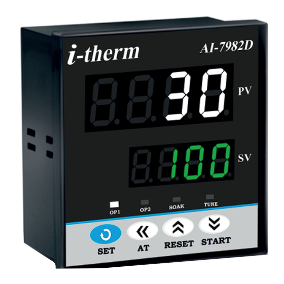
: Dual 4- Digit 7 Segment LED
4 Digit Bright White (PV)
4 Digit Luminous Green (SV)
0.56"
0.80"
0.36"
0.39"
0.56"
0.36"
: OP 1
: Main Control Output
OP 2
: Alarm Status
SOAK : Soak Timer
TUNE : Tuning Status (Only AI-7982)
: TC:J,K,R,S,N,T,B & RTD: Pt-100
i
: Refer below table.
Accuracy
Resolution
o
}
1 C
o
o
1 C
o
o
1 C
o
o
1 C
o
o
1 C
o
o
1 C
o
o
1 C
o
o
1 C
o
o
0.1 C
± 0.3 C
: 125 msec.
: 1°C/0.1°C(Only for RTD)
: Built in automatic
: Built in upto 18E max.
: 1 to 10 Sec.
: N/O, CM, N/C
: 5A @ 250VAC or 30 VDC
: > 5,00,000 operations
: Inherent
: 12V @ 30mA.
: Non-Isolated.
: Main Control output
: Programmable
1) Auxiliary control
2) Alarm
3) Soak timer
4) Alarm + Soak timer
: ON-OFF/PID (Select)
: Heat/Cool (Select)
: ----
: 0 ~50°C, 5~90% Rh
: 95% Rh (Non-condensing)
: 90~270VAC, 50/60Hz.
: 4W Maximum.
: ABS Plastic
AI-7982D
(96 X 96)
SAFETY INSTRUCTION :
This controller is meant for temperature control
applications. It is important to read the manual prior to
installing or commissioning of controller. All safety
related instruction appearing in this manual must be
followed to ensure safety of the operating personnel as
0.36"
well as the instrument.
0.36"
GENERAL
v The controller must be configured correctly for intended
operation. Incorrect configuration could result in
damage to the equipment or the process under control
or it may lead personnel injury.
v The controller is generally part of control panel and in
such a case the terminals should not remain accessible
to the user after installation.
MECHANICAL
v The Controller in its installed state must not come in
close proximity to any corrosive/combustible gases,
caustic vapours, oils, steam or any other process by-
o
± 1 C
products.
v The Controller in its installed state should not be
exposed to carbon dust, salt air, direct sunlight or
radiant heat.
v Ambient temperature and relative humidity surrounding
the controller must not exceed the maximum specified
o
limit for proper operation of the controller.
v The controller in its installed state must be protected
against excessive electrostatic or electromagnetic
interferences. Ventilation holes provided on the chassis
of the instrument are meant for thermal dissipation
hence should not be obstructed in the panel.
ELECTRICAL
v The controller must be wired as per wiring diagram & it
must comply with local electrical regulation.
v Care must be taken not to connect AC supplies to low
voltage sensor input.
v Circuit breaker or mains s/w with fuse (275V/1A) must
be installed between power supply and supply terminals
to protect the controller from any possible damage due
to high voltage surges of extended duration.
v Circuit breaker and appropriate fuses must be used for
driving high voltage loads to protect the controller from
any possible damage due to short circuit on loads.
v To minimize pickup of electrical noise, the wiring for low
voltage DC and sensor input must be routed away from
high current power cables. Where it is impractical to do
this, use shielded ground at both ends.
v The controller should not be wired to a 3-Phase supply
with unearthed star connection. Under fault condition
such supply could rise above 264 VAC which will damage
the controller.
v The Electrical noise generated by switching inductive
loads might create momentary Fluctuation in display,
alarm latch up, data loss or permanent damage to the
instrument. To reduce this use snubber circuit across
the load.
v It is essential to install a over Temp. Protection device
to avoid any failure of heating system. Apart from
spoiling the product, this could damage the process
being controlled.
1
AI-7 682D
AI-7682D
AI-7882D
(96 X 48)
(48 X 96)
OIM AI-7X82D V2.1 Page 1 of 10
Advertisement
Table of Contents

Related Manuals for i-therm AI-7482D


Summary of Contents for i-therm AI-7482D
- Page 1 USER’S OPERATING MANUAL FOR PID DIGITAL TEMPERATURE CONTROLLER (Models : AI-7482D / AI-7782D / AI-7982D / AI-7682D / AI-7882D) AI-7 682D AI-7482D AI-7782D AI-7982D AI-7682D AI-7882D (48 X 48) (72 X 72) (96 X 96) (96 X 48) (48 X 96)
-
Page 2: Mechanical Installation
The label on the controller identifies the serial number, wiring connections and batch number. OVER ALL DIMENSIONS & PANEL CUT OUT (IN MM) MODEL:- AI - 7482D/ 7782D/ 7982D TABLE : 1 Model PANEL CUTOUT AI-7482D AI-7782D AI-7982D AI-7682D MODEL : AI - 7882D AI-7882D PANEL... -
Page 3: Control List
POWER UP: At power on, following sequence will be prompted on the display till it reaches to Home display mode. In home display mode, by pressing DOWN key, User can view the set value of SP1 & SP2 (if OP2 = AUXILIARY or UPPER ALARM mode) or timer value(if OP2 = soak mode) DISPLAY... -
Page 4: Configuration List
PARA LOWER UPPER RANGE DESCRIPTION DEFAULT DISPLAY METER DISPLAY This parameter will be prompted only if selected control action is PID. This parameter allows the User to carry out Auto Tuning function below 50 % TUNE the set point. (If tune offset is set to 50 %, tuning will be carried out at 100 % OFFSET 100 %... - Page 5 PARA LOWER UPPER DESCRIPTION DEFAULT DISPLAY METER DISPLAY This parameter value is set according to the type of sensor (Thermocouple or RTD input) connected to the controller's input terminals. Sensor Type Range Accuracy Resolution INPUT TC - J TYPE TC - B 0 ~ 1800 C ±...
- Page 6 PARA LOWER UPPER DESCRIPTION DEFAULT DISPLAY METER DISPLAY If Enabled, User can View & edit the Set point (SP1) in USER list. Enable POINT 1 If disabled, User can only View the Set Point (SP1) but Can not edit it in USER list.
- Page 7 PARA LOWER UPPER DESCRIPTION DEFAULT DISPLAY METER DISPLAY Default USER LOCK CODE is 15 to access Control & Configuration List. USER User has a choice to set its own USER LOCK CODE between 1 to 9999, this is to LOCK CODE prevent unauthorized access of Control &...
- Page 8 TABLE 4 : Below listed points will appear only if O/P2 is selected as an Alarm mode. In Alarm mode, Controller continuously compares PV with either SP (for deviation or Band -alarm) or an independent Alarm set points (for process high and process low alarm). HYS2 in Control list decides when to switch OFF the Alarm. UPPER PARA LOWER...
- Page 9 TABLE 5 : Below listed option will appear only if OP2 is selected as a soak timer. UPPER PARA LOWER DESCRIPTION DEFAULT METER DISPLAY DISPLAY It defines the behaviour of the controller at the end of soak timer cycle . Options are as below.
-
Page 10: Auto Tuning Mode
AUTO TUNING MODE : To enter in this mode, Press and hold SHIFT key for minimum 3 sec. PARA LOWER UPPER DESCRIPTION DEFAULT METER DISPLAY DISPLAY This function will be executed only if selected control action is PID & Auto tune is Enable.
Need help?
Do you have a question about the AI-7482D and is the answer not in the manual?
Questions and answers