
Subscribe to Our Youtube Channel
Related Manuals for Shibaura BA-III Series


Summary of Contents for Shibaura BA-III Series
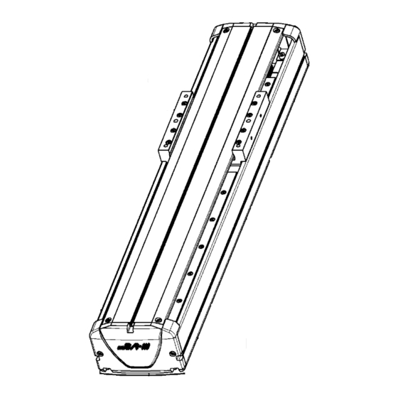
- Page 1 S E R I E S MODEL : BE30 Straight axis ACTUATOR INSTRUCTION MANUAL ACTUATOR INSTRUCTION MANUAL Original Instructions Keep this manual nearby for future reference.
- Page 2 All efforts have been made to assure the contents of this manual. If you have any questions, or find any mistakes, however, please contact Shibaura Machine. Shibaura Machine will not be held responsible for any effects caused by using this equipment, regardless of Item 3 above.
-
Page 3: Table Of Contents
Contents Chapter 1 Safety ................................1 ■1.1 Cautions for safety ............................1 ■1.2 For your safe operation ............................ 5 ■1.3 Warranty ................................9 Chapter 2 Shipment List............................. 10 ■2.1 Shipment list ..............................10 Chapter 3 Axis Specifications ........................... 11 ■3.1 Axis type and names of individual parts ......................11 ■3.2 Single axis specification .......................... -
Page 4: Chapter 1 Safety
Overview • This manual describes the axis type expression method, specifications and motor replacement procedures, etc., according to the type of axis. • For the installation, see the instruction manual (installation of actuator) provided separately. Chapter 1 Safety ■1.1 Cautions for safety ●... - Page 5 WARNING • Install the safety fences to prevent anyone from entering the working envelope of the robot. When the door is attached to the safety fence, the robot should be stopped at emergency at the same time that the door has opened. •...
- Page 6 WARNING • As the equipment is heavy, make sure of its weight and gravity center position and disconnect the cables when carrying the equipment. Also, DO NOT carry the equipment with the slider. Otherwise, the slider will move and you will get injured.
- Page 7 CAUTION • DO NOT place the equipment at a place where the ambient temperature exceeds 40°C, or where the temperature changes sharply, causing condensing, or where it is exposed to direct sunlight. Additionally, if the equipment is installed at a narrow place, the ambient temperature rises due to heat generation in the controller itself or external device, which will result in malfunction or mis-operation of the equipment.
-
Page 8: For Your Safe Operation
■1.2 For your safe operation When you use the COMPO ARM BA-III series, be sure to take the measures in conformity to the following instruction: This machine is an industrial robot in conformance to the provisions of Paragraph 31of Article 36 of the Ordinance on Industrial Safety and Hygiene. - Page 9 ■1.2.2 Precautions for installation Observe the following instructions when installing a robot: (1) The robot shall be laid out to ensure the work space required for robot teaching, maintenance and inspection. (2) The robot controller, other controllers and stationary operation panel shall be installed outside the movable range and where the operator can watch the robot operations.
- Page 10 (3) Measures to ensure the operation safety of the personnel working within the movable range Any one of the following measures or other measures on the equal or higher level shall be taken so that you can stop the robot operation immediately in the event of an error when working within the movable range: 1.
- Page 11 Requesting your cooperation For the safety instructions which seem especially important, relevant warning label is attached to the equipment. When the label attached to the equipment has peeled off or the characters are defaced and unreadable, please procure it from our sales agent in your territory by specifying the part number, and attach it to the original place.
-
Page 12: Warranty
■1.3 Warranty ■1.3.1 Warranty period This product is warranted for one of the following periods whichever comes first. (1) For 24 months after shipment from our factory. (2) For 18 months after installation at the customer's factory. (3) For 4000 hours of operation. ■1.3.2 Details of warranty (1) This product is warranted. -
Page 13: Chapter 2 Shipment List
Chapter 2 Shipment List ■2.1 Shipment list When the axis proper is shipped, it is composed of the following parts: (1) Actuator (axis) (2) Number of oval bolts attached (M6×30) The above-mentioned axs-1 will be provided with the bolts in the number shown in the right-hand Table. Axis stroke (mm) Attached quantity 100~200... -
Page 14: Chapter 3 Axis Specifications
Chapter 3 Axis Specifications ■3.1 Axis type and names of individual parts ■Type of axis The following shows the axis type: BE30F-ST-M20N-40X Series name Option None Standard Ball screw lead Motor set direction Modified product 20 mm Straight axis Frame No. 10 mm Size M 5 mm... -
Page 15: Single Axis Specification
■3.2 Single axis specification ■ Specifications Axis type BE30E-ST-- Motor AC 100-watt servo motor absolute Ball screw 15 Lead 20 mm Drive method Lead 10 mm Lead 5 mm Guide method Linear guide (Double) Bearing block ... 4 pieces Maximum payload Vertical mass Ball screw lead... - Page 16 Axis type BE30F-ST-- Motor AC 200-watt servo motor absolute Ball screw 15 Lead 20 mm Drive method Lead 10 mm Lead 5 mm Guide method Linear guide (Double) Bearing block ... 4 pieces Maximum payload Vertical mass Ball screw lead Horizontal Regeneration (Note 1) (Note 3)
- Page 17 ■ Axis dimensions [BE30E-ST-****] 100-watt absolute motor specifications Without brake BE30E-ST- BE30E-ST- BE30E-ST- BE30E-ST- BE30E-ST- BE30E-ST- BE30E-ST- BE30E-ST- BE30E-ST- BE30E-ST- BE30E-ST- BE30E-ST- M**N-15 M**N-25 M**N-35 M**N-45 M**N-55 M**N-65 M**N-75 M**N-85 M**N-95 M**N-A5 M**N-B5 M**N-C5 Type BE30E-ST- BE30E-ST- BE30E-ST- BE30E-ST- BE30E-ST- BE30E-ST- BE30E-ST- BE30E-ST-...
- Page 18 [BE30F-ST-***] 200-watt absolute motor specifications BE30F-ST- BE30F-ST- BE30F-ST- BE30F-ST- BE30F-ST- BE30F-ST- BE30F-ST- BE30F-ST- BE30F-ST- BE30F-ST- BE30F-ST- BE30F-ST- Without brake M**N-10 M**N-20 M**N-30 M**N-40 M**N-50 M**N-60 M**N-70 M**N-80 M**N-90 M**N-A0 M**N-B0 M**N-C0 Type BE30F-ST- BE30F-ST- BE30F-ST- BE30F-ST- BE30F-ST- BE30F-ST- BE30F-ST- BE30F-ST- BE30F-ST- BE30F-ST- BE30F-ST-...
-
Page 19: Chapter 4 Installing Actuator (Axis)
Chapter 4 Installing Actuator (Axis) This chapter describes the basic installation procedures for the axis and peripheral equipment. Installation shall comply with the instructions of this Chapter. If the installation procedure is incorrect, robot performance cannot be achieved. Not only that, the service life may be seriously reduced. CAUTION Precautions for installation ... -
Page 20: Installing Actuator (Axis)
■4.1 Installing Actuator (Axis) Installation shall comply with the following procedures: (1) Setting the oval bolt From the axis end face, insert the oval bolt in the T-slots of the frame installation surface. (2) Mounting on the installation base Drill installation holes on the installation base of the carriage at a pitch of approximately 150 mm, and mount the product with oval bolts. -
Page 21: Robot Type For Each Axis
■4.2 Robot type for each Axis The robot type is indicated by the 6-digit numerals specified for each robot type. If this setting is made, various parameter values suited to the axis to be used can be automatically set. The input procedure is given in Section 4.2 of the CA25 Instruction Manual (Basic Part). -
Page 22: Parameter Values
■4.3 Parameter values The parameters of this product are available in two types -- parameter 1 and parameter 2 -- depending on the frequency of use. The relationship between each parameter and the robot type is illustrated below: Setting the robot type allows the parameters on the circled portion on the left to be automatically changed. ■4.3.1 Values of parameter 1 for each robot type This parameter has a higher frequency of use. - Page 23 (Note) The Sequence of Return to Origin according to the combination format, installation conditions and others. The customer is requested to set it in conformity to your operation conditions. The initial value is common at "1" for all robot types. Thus, if there is no change, simultaneous origin return of all axes can be achieved.
-
Page 24: Chapter 5 Precautions For Use
Chapter 5 Precautions for Use ■5.1 Servo gain setting In the actuator, in order to facilitate the parameter setting work of the controller, the initial parameters for operating the component arm are automatically set by setting the "robot type" (6 digit number) determined for each model to the controller. - Page 25 (2) Speed gain (V) ● When the value is reduced ・ If it is made too small, an error such as "overflow error" may occur during operation (especially when accelerating) and operation may not be possible. ・ The positioning and holding force of the slider is reduced. (Rigidity decreases) ●...
- Page 26 ■5.1.2 About adjustment of servo gain When adjusting the servo gain, refer to the contents described in ■ 5.1.1 "Servo gain setting value and operating condition" and set according to the following description. (1) Speed gain setting The initial value of speed gain usually does not need to be changed. If it is changed, please set as follows.
- Page 27 ● Abnormalities such as vibration and abnormal noise may occur due to resonance, so check the operation from the low speed range used for return to origin operation and "JOG" operation to the high speed range used for continuous operation. ●...
-
Page 28: Chapter 6 Maintenance
Chapter 6 Maintenance ■6.1 Precautions for inspection and maintenance work (1) Precautions for inspection and maintenance work Observe the following instructions at the time of inspection and maintenance: 1. The robot shall be inspected and maintained by the personnel having a sufficient level of skill and experience. If such personnel are not available, contact the manufacturer and request implementation of the relevant work or education of the person in charge. -
Page 29: Inspection Before Starting The Work
■6.2 Inspection before starting the work (1) Before starting your work with the robot, make sure of the following: 1. Brake device function 2. Emergency stop device function 3. Contact preventive equipment and robot interlock function 4. Related devices/robot interlocking function 5. -
Page 30: Maintenance Schedule
■6.4 Maintenance Schedule Perform the pre-work inspection before starting work on a daily basis. Periodic inspections and maintenance performed after a certain period of time should be performed in units of 1200 hours (operating hours). Also, please carry out overhaul every 24000 hours (operating hours). 1200 3-month check 2400... - Page 31 ■6.4.1 Maintenance and inspection items by schedule Determine the schedule for Inspection before starting the work and periodic inspection and maintenance. (1) Inspection at Power OFF I: Inspection before starting the work Q: Quarterly inspection S: Semi-annual inspection A: Annual inspection Description Inspection point ○...
-
Page 32: Cleaning
■6.5 Cleaning Clean the robot proper. Clean the robot proper in conformity to the following steps: 1. Turn off the power switch and remove the power plug. 2. Use waste cloth or such to remove the dust and dirt from the frame and covers etc. 3. -
Page 33: Motor Replacement Procedure
■6.7 Motor replacement procedure Replace the motor according to the following steps: (1) Remove the frame cover and end plate. End plate End cover Frame cover Turn OFF power before starting the work. CAUTION (2) Loosen the bolt on motor output shaft side of the coupling. (Do not loosen the bolt on the ball screw side). Motor mounting screw Bolt on motor output shaft side ... - Page 34 (3) Remove the motor from the axis. (4) Mount a new motor on the same position. (Mount it so that the motor lead wire will be located on the bottom side). (Do not tighten the coupling fixing bolt in this stage.) (5) Connect the axis and controller on a temporary basis.
-
Page 35: Origin Position Adjustment
■6.8 Origin position adjustment Adjust the origin according to the following procedure: (1) When the origin sensor is ON (Note), slider positions shall have the following relationship at the origin. Sensor installation Origin sensor ON position Reference origin position reference position (Note) Applicable axis BE30E-ST-M10 (20) - Page 36 [Slide position checking procedure when origin sensor is turned ON] Turn OFF the controller power, and move the slider 50 to 100 mm from the origin. After that, turn ON the power and return the axis to the origin. (In case of the axis with a brake, turn ON the power. After that, use the jog mode for this operation.) ...
-
Page 37: Replacement Of Ball Screw
■6.9 Replacement of ball screw If the replacement of ball screw needs to be replaced, contact our sales office closest to your company. It must not be replaced by the customer. This replacement is performed for each axis. It should be noted that this replacement cannot be made inside the device or in the combined state. -
Page 38: Chapter 7 Spare Parts
Chapter 7 Spare Parts ■7.1 Spare Parts When a trouble has occurred to the robot proper and you have found it out at an earlier stage, you cannot repair it if you have no repair parts. Accordingly, you are recommended to keep spare parts on hand. Parts number Parts name Remarks... - Page 39 TOKYO HEADQUATERS Equipment Electronic Sales Group, Control Systems Division 2-2, Uchisaiwaicho 2-Chome, Chiyoda-ku, Tokyo 100-8503, Japan TEL: [81]-(0)3-0270 FAX: [81]-(0)3-3509-0335 Q3245E 08 Jan. 2023...
Need help?
Do you have a question about the BA-III Series and is the answer not in the manual?
Questions and answers