Table of Contents
Advertisement
Quick Links
Advertisement
Table of Contents

Related Manuals for Bosch 1200 Series


Summary of Contents for Bosch 1200 Series
- Page 1 1200 Series IP Video Storage System Installation Manual...
-
Page 2: Table Of Contents
1200 Series IP Video Storage System Table of Contents | en Table of Contents Safety Instructions Overview Warnings and Precautions Preparing for Setup Electrical Safety Precautions General Safety Precautions System Safety System Overview System Interface Control Panel Buttons Control Panel LEDs... -
Page 3: Safety Instructions
Preparing for Setup The 1200 Series chassis contains many features that are unique to the 1200 Series chassis model. Read this manual in its entirety before beginning the installation procedure. Electrical Safety Precautions... -
Page 4: General Safety Precautions
1200 Series IP Video Storage System Safety Instructions | en – DVD-ROM laser: CAUTION - This server may have come equipped with a DVD-ROM drive. To prevent direct exposure to the laser beam and hazardous radiation exposure, do not open the enclosure or use the unit in any unconventional way. -
Page 5: System Overview
FB-DIMM memory modules, and four hot-swap drive bays offer maximum storage capacity. For information on supported hardware, see the datasheet for the 1200 Series in the Bosch Online Product Catalog. For more detailed technical information on your device refer to http:// www.supermicro.com/support/manuals/index.cfm. -
Page 6: System Interface
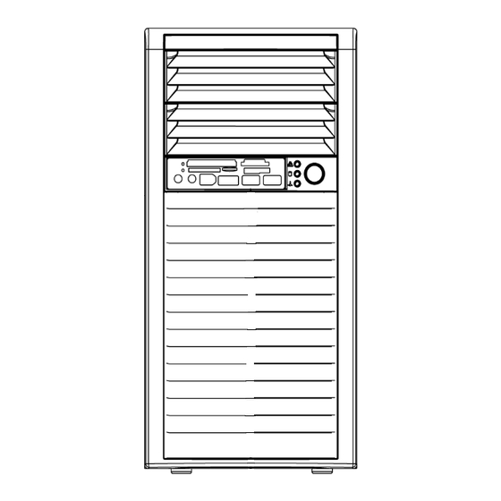
Control Panel LEDs The control panel located on the front of the 1200 Series chassis has three LEDs. These LEDs provide you with critical information related to different parts of the system. This section Bosch Sicherheitssysteme GmbH Installation Manual DOC | V1 | 2010.08... - Page 7 | System Interface 1200 Series IP Video Storage System explains what each LED indicates when illuminated and any corrective action you may need to take. HDD: Indicates IDE channel activity. SAS/SATA drive activity when flashing. NIC1: Indicates network activity on GLAN1 / 2 when flashing.
-
Page 8: Installation
1200 Series IP Video Storage System Installation | en Installation The systems comes pre-installed and only hard drives may be exchanged onsite. In case of any other failure the entire system has to be exchanged (by advanced exhange). Bosch Sicherheitssysteme GmbH Installation Manual DOC | V1 | 2010.08... -
Page 9: Chassis Setup And Maintenance
This chapter covers the steps required to install components and perform maintenance on the chassis. Most components of the 1200 Series do not require tools or screws to set them up. Those components which must be secured with screws require only a Phillips screwdriver. -
Page 10: Rotating The Hard Drive Cage
Lift the release tab (A). Rotate the hard disk drive cage (B) outward. Removing and Installing Hard Drives The 1200 Series chassis must be powered-down before hard drives can be removed from the hard drive carriers. Removing and Installing Hard Drives Disconnect the chassis from any power source. - Page 11 | Chassis Setup and Maintenance 1200 Series IP Video Storage System Gently slide the hard drive carrier out of the hard drive cage. If a hard drive is already present, remove it by carefully pulling the sides of the hard drive carrier outward.
-
Page 12: Installing The I/O Shield And Motherboard
1200 Series IP Video Storage System Chassis Setup and Maintenance | en 10. If desired, each hard drive carrier may be secured to the exterior of the hard drive cage using optional screws. 11. Rotate the hard drive cage 90 degrees inward, returning it to the closed, operational position in the chassis. -
Page 13: A Appendix
| Appendix 1200 Series IP Video Storage System Appendix Motherboard layout JPUSB1:B/P USB WAKE UP KB/MOUSE JPI2C:PWR I2C 1-2:ENABLE 2-3:DISABLE FLOPPY JPW1 JPUSB1 JTPM JI2C1 JI2C2 SLOT7 PCI-E X8 GEN2 JI2C1/JI2C2 ON:Enable OFF:Disable SLOT6 PCI-E X8 GEN2 SLOT5 PCI-E X4 on X8... - Page 14 1200 Series IP Video Storage System Appendix | en X8SIL/X8SIL-F/X8SIL-V Jumpers Number Jumper Description Default JPUSB1 BP USB0/1 Wake-up Pins 1-2 (Enabled) JBT1 CMOS Clear JPES Energy Saving Feature Pins 2-3 (Disabled) 13,14 JI2C1/JI2C2 SMB to PCI Slots JPG1 Onboard VGA Enable...
- Page 15 | Appendix 1200 Series IP Video Storage System Floppy Floppy Disk Drive connector Alarm Reset Speaker header (Pins 3/4: Internal, 1~4:External) Front Panel Control header Chassis Intrusion header JLED Power LED Indicator header JPW1 24-pin ATX main power connector (required)
- Page 16 1200 Series IP Video Storage System Appendix | en Network Connections Two Intel 82574L Gigabit (10/100/1000 Mb/s) Ethernet Controllers for LAN 1 and LAN 2 ports. Two (2) RJ-45 Rear IO Panel Connectors with Link and Activity LEDs Single Realtek RTL8201N PHY to support IPMI 2.0 (X8SIL-F...
- Page 17 | Appendix 1200 Series IP Video Storage System CPU/System overheat LED and control CPU Thermal Trip support Thermal Monitor 2 (TM2) support Fan Control Fan status monitoring with firmware 4-pin (Pulse Width Modulation) fan speed control Low noise fan speed control System Management PECI (Platform Environment Configuration Interface) 2.0...
-
Page 18: Chipset Overview
1200 Series IP Video Storage System Appendix | en Note: This is a general block diagram and may not exactly represent the features on your motherboard. See the Motherboard Features pages for the actual specifications of each motherboard. Chipset Overview The X8SIL/X8SIL-F/X8SIL-V supports the Intel Xeon 3400 processor series. -
Page 19: Power Configuration Settings
| Appendix 1200 Series IP Video Storage System pre-defined overheat threshold, the CPU thermal trip feature will be activated and it will send a signal to the buzzer and, at the same time, the CPU speed will be decreased. -
Page 20: Iscsi Support
1200 Series IP Video Storage System Appendix | en drives. The Super I/O supports two 360 K, 720 K, 1.2 M, 1.44 M or 2.88 M disk drives and data transfer rates of 250 Kb/s, 500 Kb/s or 1 Mb/s. - Page 21 | Appendix 1200 Series IP Video Storage System DOC | V1 | 2010.08 Installation Manual Bosch Sicherheitssysteme GmbH...
- Page 23 Bosch Sicherheitssysteme GmbH Werner-von-Siemens-Ring 10 85630 Grasbrunn Germany www.boschsecurity.com © Bosch Sicherheitssysteme GmbH, 2010...
Need help?
Do you have a question about the 1200 Series and is the answer not in the manual?
Questions and answers