Advertisement
Quick Links
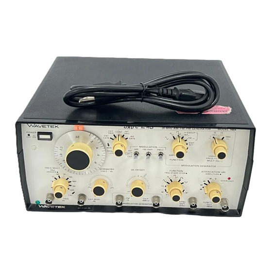
INSTRUCTION MANUAL
MODEL 148A
2 0 MHz
AM/FM/PM GENERATOR
- 1981. - Wavetek
THIS DOCUMENT CONTAINS INFORMATION PRO-
PRIETARY TO WAVETEK AND IS SOLELY FOR IN-
STRUMENT OPERATION AND MAINTENANCE. THE
INFORMATION IN THIS DOCUMENT MAY NOT BE
DUPLICATED I N ANY MANNER WITHOUT THE
PRIOR APPROVAL IN WRITING OF WAVETEK.
SAN DIEGO
9045 Balboa Ave., San Diego, CA 92123
P.O. Box 661, San Diego,
Tel
.
92112
Advertisement

Related Manuals for Wavetek 148A


Summary of Contents for Wavetek 148A
- Page 1 2 0 MHz AM/FM/PM GENERATOR - 1981. - Wavetek THIS DOCUMENT CONTAINS INFORMATION PRO- PRIETARY TO WAVETEK AND IS SOLELY FOR IN- STRUMENT OPERATION AND MAINTENANCE. THE INFORMATION IN THIS DOCUMENT MAY NOT BE DUPLICATED I N ANY MANNER WITHOUT THE PRIOR APPROVAL IN WRITING OF WAVETEK.
-
Page 2: Specifications
Generator is quiescent until trig- gered by an external signal, then generates one cycle at the selected frequency. Wavetek Model 148A, 20 MHz AM/FM/PM Generator is a precision source of sine, triangle, square, ramp External Gate: Same as external trigger, except gen- and pulse waveforms plus dc voltage. - Page 3 peak current and may be attenuated to 60 dB in 20 center by an amount determined by the modulation steps. An additional 20 dB vernier also controls the amplitude. w a v e f o r m a m p l i t u d e s . -Phase Modulation (PM): As in External Modulation.
- Page 4 Output 1.2.2.3 1.2.1 .12 Frequency Precision Dial Accuracy are fixed level 10V p-p balanced about ground. M and are fixed level 5 Vp of setting + 1 % of full range) on x 100 thru from 0 to + 5V. x 1 M ranges.
-
Page 5: Controls And Connectors
S E C T I O N O P E R A T I O N 3.1 CONTROLS AND CONNECTORS b. EXT TRIG Mode - Same as for EXT GATE mode, except the main generator output is numbers are keyed to figure 3-1. The following item one cycle of selected signal only. - Page 6 AM - The instantaneous amplitude of the out- 3.1.2 Modulation Generator put signal varies with the instantaneous ampli- FUNCTION Switch - This switch selects the tude of the modulation signal. waveform output of the modulation generator. Output is at the OUT BNC connector and is FM - The instantaneous frequency of the out- also available internally to the main generator.
- Page 7 set up the generator for continuous operation (refer to 3.2.4 Manual Triggering and Gating paragraph 3.2.1). The main generator may be trig- gered internally by the modulation generator or trig- can also be used The TRIGGER LEVEL control gered by an external source. If an unmodulated manually triggering or gating the generator.
- Page 8 OUTPUT modulating signal (observing 5 Vp limit) to set the car- FREQUENCY MAIN DIAL rier level. SETTING AMPLlTUDE MOD IN FACTOR* 3.2.6 FM Operation 2.0- In FM operation, the instantaneous frequency of the 1.8. output signal varies with the instantaneous amplitude of the modulating signal.
- Page 9 AM - The instantaneous amplitude of the out- 3.1.2 Modulation Generator put signal varies with the instantaneous ampli- FUNCTION Switch - This switch selects the tude of the modulation signal. waveform output of the modulation generator. Output is at the OUT BNC connector and is FM - The instantaneous frequency of the out- also available internally to the main generator.
- Page 10 set up the generator for continuous operation (refer to 3.2.4 Manual Triggering and Gating paragraph 3.2.1). The main generator may be trig- gered internally by the modulation generator or trig- can also be used The TRIGGER LEVEL control gered by an external source. If an unmodulated manually triggering or gating the generator.
- Page 11 OUTPUT modulating signal (observing 5 Vp limit) to set the car- FREQUENCY MAIN DIAL rier level. SETTING AMPLlTUDE MOD IN FACTOR* 3.2.6 FM Operation 2.0- In FM operation, the instantaneous frequency of the 1.8. output signal varies with the instantaneous amplitude of the modulating signal.
- Page 12 3.2.8 PM Operation signal. When the main generator is set above a range midpoint, the modulation signal begins to lose its ef- fectiveness. The effect is that the input signal is rolling In PM operation, the instantaneous phase of the out- off at 6 dB/octave due to form factor limitations of the put signal varies with the instantaneous change in input differentiator.
- Page 13 selector and by the magnitude of the currents sup- 4.1 FUNCTIONAL BLOCK DIAGRAM ANALYSIS plied to and removed from it. Since the currents are linearly proportional to the sum of VCG inputs, so will This section describes the functions of major circuit be the output frequency.
- Page 14 The signal shaper contains switching elements and a While the integrating capacitor is being held from diode array for signal conditioning the buffered charging, the start/stop diode must sink the current source, which has a magnitude variable with VCG in- triangle and square inputs into the various waveforms puts.
-
Page 15: Circuit Analysis
across series resistors to the supplies equal to the tion for an external signal to the switches “external” control voltages. The FET currents will be switched at positions. the diode gate into a timing capacitor to produce the triangle waveform. The FM and PM switches provide VCG inputs. - Page 16 VE RNIER SYMMETRY Figure 4-3. VCG Simplified Schematic...
- Page 17 (multiplier 1 K) by switching 500 resistors in parallel a matched duplicate FET, Q9. Q9 has the identical with the 5 basic current setting resistors R326, drain current as Q8 and, therefore, the same gate-to- R38, R48 and R330 producing the output frequencies source voltage.
- Page 18 same voltage. The simplified timing diagram il- diode network presenting a square wave input voltage lustrated in figure 4-2 shows these points as one ter- to the multiplier. minal at C. When the hysteresis switch output is Transconductance Multiplier positive, CR16 is forward biased, so that the current 4.2.10 sink is sourced by the drive circuit and is ineffective.
- Page 19 which is the output voltage, will start to go negative. tion amplifies the positive swing of the output, while Finally, when the output has moved far enough the lower mirror portion amplifies the negative swing. negative to pull point A back to zero, by pulling current Operation is class AB;...
- Page 20 clipped by forward biasing CR1; the negative portion Other circuit components are shown on the main board schematic, sheet 3. Emitter followers Q46 and is clipped by CR2. While CR1 is on, Q1 conducts and Q48 increase the driving power to the bases of Q47 Q3 switches off to a TTL low level.
- Page 21 the start/stop diode are matched and carry equal cur- signal at CR24 is held low, and the trigger amplifier rents, the trigger baseline will be stable with varying output is held high for the trigger duration. The last VCG inputs. triangle cycle started is completed through the action explained in trigger mode.
Need help?
Do you have a question about the 148A and is the answer not in the manual?
Questions and answers