Table of Contents
Advertisement
Perkins Electro-Acoustic Research Lab, Inc.
Please note that the links in the P
and can be used to direct your web browser to our site or to
open an e-mail message window addressed to ourselves.
To see the feedback we have left for our customers,
This document has been prepared as a public service . Any and all trademarks
and logotypes used herein are the property of their owners.
It is our intent to provide this document in accordance with the stipulations with
respect to "fair use" as delineated in Copyrights - Chapter 1: Subject Matter and
Scope of Copyright; Sec. 107. Limitations on exclusive rights: Fair Use.
Public access to copy of this document is provided on the website of Cornell Law School
at
http://www4.law.cornell.edu/uscode/17/107.html
Notwithstanding the provisions of sections 106 and 106A, the fair use of a copyrighted work, includ-
ing such use by reproduction in copies or phono records or by any other means specified by that section,
for purposes such as criticism, comment, news reporting, teaching (including multiple copies for class-
room use), scholarship, or research, is not an infringement of copyright. In determining whether the use
made of a work in any particular case is a fair use the factors to be considered shall include:
1 - the purpose and character of the use, including whether such use is of a
commercial nature or is for nonprofit educational purposes;
2 - the nature of the copyrighted work;
3 - the amount and substantiality of the portion used in relation to the copy-
righted work as a whole; and
4 - the effect of the use upon the potential market for or value of the copy-
righted work.
The fact that a work is unpublished shall not itself bar a finding of fair use if such finding is made
upon consideration of all the above factors
Web:
http: // www. pearl - hifi . com
E-mail:
custserv @ pearl - hifi . com
Inc.
To view our item listings on eBay,
Sec. 107. - Limitations on exclusive rights: Fair Use
♦
86008, 2106 33
Ph: + .1.403.244.4434
❦
Engineering and Intuition Serving the Soul of Music
logotype above are "live"
EARL
click here.
and is here reproduced below:
PDF Cover Page
♦
Ave. SW, Calgary,
AB; CAN T2T 1Z6
Fx: + .1.403.245.4456
click here.
Advertisement
Table of Contents

Related Manuals for Wavetek 182A


Summary of Contents for Wavetek 182A
- Page 1 Web: http: // www. pearl - hifi . com Ave. SW, Calgary, 86008, 2106 33 AB; CAN T2T 1Z6 Ph: + .1.403.244.4434 Fx: + .1.403.245.4456 E-mail: custserv @ pearl - hifi . com Inc. ❦ Perkins Electro-Acoustic Research Lab, Inc. Engineering and Intuition Serving the Soul of Music Please note that the links in the P logotype above are “live”...
- Page 2 Verso Filler Page ♦ ♦...
- Page 4 Verso Filler Page...
- Page 5 STRUMENT OPERATION AND MAINTENANCE. THE INFORMATION IN THIS DOCUMENT MAY NOT BE DUPLICATED IN ANY MANNER WITHOUT THE PRIOR APPROVAL IN WRITING OF WAVETEK. Vv' AVETE� WAVETEK SAN DIEGO, INC. 9045 Balboa Ave., San Diego, CA 92123 P. O. Box 85265, San Diego, CA 92138...
- Page 6 The obligation of Wavetek arising from a Warranty claim shall be limited to repairing, or at its option, replacing without charge, any product which in Wavetek's sole opinion proves to be defective within the scope of the Warranty. In the event Wavetek is not able to modify, repair or replace non-conforming defective parts or...
-
Page 7: Table Of Contents
CONTENTS SECTION 1 GENERAL DESCRIPTION THE MODEL 182A..........SPECiFiCATIONS ..........1.2.1 Versatility ..........1.2.2 Frequency Precision........1.2.3 Amplitude Precision........1.2.4 Waveform Characteristics........1.2.5 General ............ SECTION 2 INSTALLATION MECHANICAL INSTALLATION........ ELECTRICAL INSTALLATION......... 2.2.1 Power Connection.......... 2.2.2 Signal Connections......... ELECTRICAL ACCEPTANCE CHECK...... - Page 8 SAFETY This instrument is wired for earth grounding via the facility power wiring. Do not bypass earth grounding with two wire extension cords, plug adapters, etc. BEFORE PLUGGING IN the instrument, comply with installation instructions. MAINTENANCE may require power on with the instrument covers removed. This should be done only by qualified personnel aware of the electrical hazards.
-
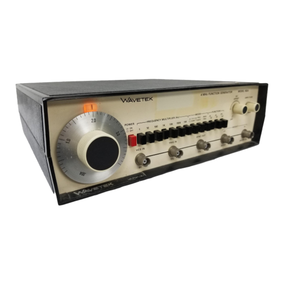
Page 9: The Model 182A
"v selectable and variable to 20V p-p Wavetek Model 182A Four M Hz Function Generator is (1 OV p-p into 500) H I output, and to 2V p-p (1 V p-p into a precision source of sine, triangle and square wave... -
Page 10: Waveform Characteristics
1.2.4 Waveform Characteristics Dimensions 28.6 cm (11 � in.) wide; 8.9 cm (3Y2 in.) high; 26.7 Sine Distortion (10Y2 in.) deep. Less than: 0.5% on x 1K and x 10K ranges; 1% on X1, X10, Weight X 100 and x 1 OOK ranges. All harmonics 25 dB below 2.7 kg (6 Ib) net;... -
Page 11: Installation
FREQUENCY MULTIPLIER ....ment and the facility power outlet for a continuous earth ground path. The earth Set up the oscilloscope, Model 182A and external ground path can be identified at the function generator as shown in figure 2-1 and perform plug on the instrument power cord;... - Page 12 If simultaneous 6000 and 500 output impedances are desired: MOD EL 182A TIL OUT OSCILLOSCOPE Change value of R148 from 4990 to 6040. Remove R149. SYNC The result is: HI 10V p-p (500 source) into 500. LO 10V p-p (6000 source) into 6000.
-
Page 13: Controls And Connections
SECTION OPERATION TRIG pressed. DC level output CONTROLS AND CONNECTIONS until generator triggered by the MAN TRI G The generator front panel controls and connectors are or with a signal at the TRIG IN connector shown in figure 3-1 and keyed to the following descrip When triggered, the generator output is one cycle tions. -
Page 14: Signal Termination
20 dB (1/10) lower in amplitude. TIL OUT Connector - A TTL square for each RECEIVING cycle of the generator. To be used for syn MODEL 182A INSTRUMENT chronization or as a TTL signal capable of driv EFFECTIVE OUTPUT ing 20 TTL loads. -
Page 15: Voltage Controlled Function Generator Operation
Voltage Controlled Function Generator 3.2.3 four times the multiplier setting, and the Operation lower limit is 111000 t h of the upper limit. Operation as a voltage controlled function generator OUTPUT MAIN DIAL FREQUENCY VCG IN is as for a manually controlled function (VCG) SETTING FACTOR... -
Page 17: Circuit Description
SECTION CIRCUIT DESCRIPTION FUNCTIONAL BLOCK DIAGRAM ANALYSIS capacitor by 10) for each of the lower multiplier ranges. This section describes the functions of major circuit elements and their relationships to one another as The TIL square from one side of the comparator is shown in figure 4-1, functional block diagram. - Page 18 and, when the OV baseline level is reached, the in the gated mode. This is identical to the triggered generator loop again stops. The result is a single mode, except the trigger flip-flop is held high for the waveform generated after the triggering signal cor full duration of the triggering signal.
-
Page 19: Section Alignment
ALIGNMENT FACTORY REPAIR After referring to the following preliminary data, perform Wavetek maintains a factory repair department for those alignment, as necessary, per table 5-1. If performing par customers not possessing the necessary personnel or tial alignment, check previous settings and adjustments test equipment to maintain the instrument. - Page 20 Table 5·1 . Alignment Procedure (Continued) Test Control Step Check Tester Point Setting Remark Adjust Result Approximate Counter 500 OUT Dial: .004 20 ms Bottom of HI (termin- F REQ MUL T: period the Dial ate into Frequency Set scope to ( -) trigger; Bottom Scope Equalize...
- Page 21 - 1 5 � /.- ... , O NlY " El E2 E3 1 88 o 00 � '_ .. " � l al l _E A �GIC � D " -Q l - � • � 1 5 � 8 8 V "5�"...
- Page 22 Verso Filler Page...
-
Page 23: Section 6 Troubleshooting
TROUBLESHOOTING 6.3.2 FACTORY REPAIR Diode Wavetek maintains a factory repair department for A diode (except a zener) is defective if there is greater those customers not possessing the necessary per than one volt (typically 0.7 volt) forward voltage sonnel or test equipment to maintain the instrument. If across it. -
Page 24: General Instructions
GENERAL INSTRUCTIONS which best describes the malfunction and proceed to the referenced troubleshooting table. When encountering a problem, it is advisable to return Follow through the checks in the troubleshooting table, as many of the front panel controls as possible to their using schematics and assemblies as a guide. - Page 25 Table 6·2. Power Supplies and Generator Loop (Continued) Indication: Fuse blown, no power indication or no outputs. Check If Faulty, Check Check U7 pin 14 for + 5 Vdc and U7 pin 13 for - 5 Vdc. a. 04, 03, U2. b.
- Page 26 6·4. Table Sine Conversion Indication: Sine waveform problem. Check Check Faulty, Set controls to initial positions (refer to paragraph 6.4). Check for normal operation. Check emitter 01 for a 4 kHz, ± 1.25V triangle. Go to table 6-2. Verify that the ±...
- Page 27 Table 6·7. VCG Circuit Indication: Generator does not respond correctly to dial and VCG input. Check Faulty, Check Set controls to initial positions (refer to paragraph 6.4). Check for normal operation. Check for approximately + 15V at E11. a. E10, E11 and E12 wiring. b.
- Page 28 6·8. Table Symmetry Indication: Waveform symmetry problem. Check If Faulty, Check Set controls to initial positions (refer to paragraph 6.4). Check for normal operation. If symmetry problem appears on x 1, X 10, X 100 ranges only, problem may be R90 adjustment or go to table 6-9. Perform steps 5 through 12 of table 6-7, then return to this table.
- Page 29 Table 6·10. Trigger Logic Indication: Generator trigger and gate mode problems. Check If Faulty, Check Set controls to initial positions (refer to paragraph 6 .4). Check for normal continuous operation. If generator operates normally in continuous mode, go to step 7. Check for OV at U9 pins 2 and 5.
- Page 30 Verso Filler Page...
-
Page 31: Section 7 Parts And Schematics
Wavetek instrument as quickly as develop ment and testing permit. Because of the time needed to compose and print instruction manuals, it is not... - Page 32 FINISH THIS c::GWf AM PROP'lUETARV .,.fOR· DOC.lMIENT WAVUE!< PROCESS IllA T ION OESIGN RIGHTS BELONGING MAY NOT FOR AIf'( WAVETEK AND IE REPRODUCED 00 �OT $(:Ali5 DW� ____ __ __ MOOEl DWGNO. IBcA 0004 -OO-PJ65 RtASON EXCEPT CALIBRATION, OI"ERATIOH, NOH:...
- Page 33 THIS DOCI..UE NT INFOR· MATION DESIGN CONTAINS "'OPRIETARY FOR ANY TRAN5FORMER PRIMARY WIRING RIGHTS BELONGING REASON EXCEPT WAVETEK AMlIlAY NOT IE REPRODUCED DETAIL �" IlAINTENANCE CALIBRATiON. OPERATiON. NOTE: TERNINALS WlTMOUT WRITTEN AuntORlZATtON.. APPLY BEND TOP INSULATE (REF.) IN,SOlDER,AND . SI-IOWN "...
- Page 34 .XX !.QlO ANGLES 182A THIS DOCUMENT CONTAINS PROPRIETARY INFOR- WAVETEK PROCESS PAQE: DESIGN RIGHTS BELONGING SCALE DWO I��� 23338 MATION MODEL NO. WAVETEK AND MAY NOT BE REPRODUCED FOR ANY ��&����U;Cul'MS$ REASON E"XCEPT CALIBRATION OPERATION. AND MAINTENANCE WITHOUT WRITTEN AUTMQRIZATION. SHEET...
- Page 35 SYNC 2751 OATE .". 'N2404 POWER SUPPLY 'LoGi C l tlOT TRIGGER 101( 74L500 SWI I 2.21K TlJ.7K lOOK -15V PRE-AMP 2.21K +15V .005 RI31 17.4K TL084 7./51( 33.2 R I 3 4 5.761( ":' 4.02K -15 V CAPS � RI39 RI 4 4 CRZ3 JaW...
- Page 36 " El E2 E3 " " , .Ql � D� � � ° ' " � f£� '" - .w- � ' I � -C26- " • � S Y N C - m. - _ •• - + 5 V .!.
- Page 37 91ARI00 BECK 4600-0 -Ol03 R119 RES. MF. lISW. IX. 1, 96K RN55D-1961F 4701-03-1961 NONE WVTK 1207-00-2069 ABSY. COAX 182A-0817 IB2A-2069 R19 R90 POT. TRIM. 10K 91ARIOK BECf( 4600-0f -0315 R132 R136 R15 R46 R'7 RES.I'1F. I/BW. IX. RN55D-2ooIF 4701-03-2001 NONE ASSY.
- Page 38 OTHE RWISE SPEC IF lEO INFOR· FINISH .xx �.030 ANGLES WAVETEK PROCESS THIS DOCUMENT CONTAINS PROPRIETARY I�� 23338 MATiON DESIGN RIGHTS BELONGING , AND WAVETEK AND MAY NOT BE REPAOOUCED FOR WftITTEN RE.AS()N EXCEPT CALtBflATION, MAINTENANCE WITHOUT AuTHORIZATtoN. SHEET _ ...
Need help?
Do you have a question about the 182A and is the answer not in the manual?
Questions and answers