
Related Manuals for J&E Hall JABC-1


Summary of Contents for J&E Hall JABC-1
- Page 1 CELLAR COOLER RANGE TECHNICAL MANUAL JABC-1 AMBIENT BEVERAGE COOLER ISSUE: 01.06.2023...
-
Page 2: Table Of Contents
IMPORTANT! By ensuring this product is disposed of correctly, you will help to prevent potential negative consequences for the environment and human health. Please contact J & E Hall READ BEFORE PROCEEDING! for more information. Batteries must be removed from the controller if applicable GENERAL SAFETY GUIDELINES and disposed of separately in accordance with relevant local and national legislation. -
Page 3: Nomenclature
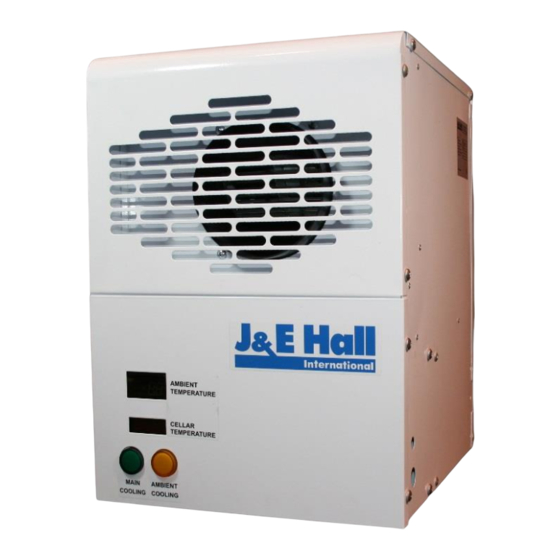
Product Features Screw 2 pcs M5 Nylon Flat Washer 2 pcs The JABC-1 is primarily used for cooling beer cellars. Cold Cable Glands M12 3 pcs air is drawn from outside by the fan through the washable Fixing Hole Template 1 pcs air filter and distributed into the cellar space. -
Page 4: Health And Safety
The JABC unit comes with a rear entry air inlet connection Health and Safety for direct attachment to an external facing wall (through- wall installation). If an external facing wall is unavailable, General information the JABC unit can be mounted in a suitable location, with the air inlet connection changed to bottom entry. -
Page 5: Installation
Figure 4: Side View - Air Inlet Hole Through Wall Installation 1. Ensure that the outside wall is clear of any obstructions. 2. Ensure that the selected wall is strong enough to support the unit. 3. Ensure that no other exhausts will blow directly into the air inlet duct. -
Page 6: Electrical Connection
10°C. This must not be altered. 4. Make sure that the supply to the JABC-1 unit and the 4. The temperature set point of the main cooling should control circuit from the main cellar cooler are using the be set at 10°C to match the JABC controller or it can... -
Page 7: Appendix
Probe short circuited Maximum temperature alarm Minimum temperature alarm Figure 7: Outline Drawing Figure 8: Wiring Diagram MODEL JABC-1 NOTE 1: REMOVE JUMPER WIRE P2-P3 FROM JCC, TO CONNECT WIRE FROM P2-P3 TO A-B OF JABC UNIT. XT121C XR04CX 8(3)A/250V... -
Page 8: Service & Maintenance
Service & Maintenance Disconnect the mains electrical supply before servicing or opening the units. The units are designed to give long life operation with minimum maintenance. However, they should be routinely checked, and the following service schedule is recommended under normal circumstances: Slide the filter out The front panels and control panel need to be removed to ensure all parts / components mentioned below are... - Page 9 Figure 10: Declaration of Conformity Issue: 01.06.2023 Page 7...
- Page 10 Figure 11: EU Declaration of Conformity Issue: 01.06.2023 Page 8...
- Page 11 THIS PAGE IS LEFT BLANK INTENTIONALLY Issue: 01.06.2023 Page 9...
- Page 12 RJ0110030007337 J & E Hall Limited Hansard Gate West Meadows Derby, DE21 6JN England Tel: + 44 (0) 1332 253400 Fax: + 44 (0) 1332 371061 Email: helpline@jehall.co.uk www.jehall.com Issue: 01.06.2023...
Need help?
Do you have a question about the JABC-1 and is the answer not in the manual?
Questions and answers