Table of Contents

Subscribe to Our Youtube Channel
Related Manuals for SincMill SCM-180

Summary of Contents for SincMill SCM-180
- Page 1 Attention: Please read this manual carefully before using the machine. SCM-180 Contents Performance Home Gym Safety Information Components-Parts Components-Fixings Assembly Instructions Parts List Model: SCM-180 Please keep this manual for your query. 2022-09-27...
-
Page 2: Table Of Contents
Contents Before you Begin Safety Information Components-Fixings Components-Parts Assembly Instructions 7-26 Explosion diagram Workout Area 29-35 Exercise Information Parts List 36-39... -
Page 3: Before You Begin
Before you Begin Thank you for selecting SCM-1150 Multi Purpose Home Gym. For your safety and benefit, read this manual carefully before using the machine. As a manufacturer, we are committed to provide you complete customer satisfaction. If you have any questions, or find there are missing or damaged parts, we guarantee you complete satisfaction through direct assistance from our factory. -
Page 4: Safety Information
Safety Information Important – Please read fully before assembly or use Warning for optimum safety This equipment is built however we still remind you to read the entire manual before you assemble or operate the 12. Select an appropriate weight plate to machine. -
Page 5: Components-Fixings
Components - Fixings (1) - Page 6 Components - Fixings (2)
-
Page 7: Components-Parts
Components - Parts (1) - Page 8 Components - Parts (2)
-
Page 9: Assembly Instructions
Assembly Instructions Tools: Adjustable spanner x 2 Attention: It is strongly recommended to assemble the equipment by two or more people, otherwise it may cause serious injury. The icon indicates the spanner can be directly used to tighten and secure during assembly. - Page 10 Step 1 1. Put the Guild Rod (5) through 2 x Rubber Bumpers (65) from bottom, and then insert the Guide Rod (5) into the Rear Base Frame (2), and secure with 2 x M10×25mm Allen Bolts (92) and 2 x M10 Washers (100).
- Page 11 Step 2 1. Connect the Base Frame (3), Bracket (31) to the Front Vertical Frame (1) using 2 x M10×90mm Carriage Bolts (85), 2 x M10 Washers (100),2 x M10 Spring Washers (99) and 2 x M10 Aircraft Nuts (102). Please refer to Diagram A. 2.
- Page 12 Note: #65 is a shock absorbing rubber pad. #34 has the large U-shaped groove facing down and the small U-shaped groove facing up. Step 3 1. Sequentially put the Guide Rod (5) through the 15 pieces Weight Plates (34) , insert the Selector Rod (19) into the central hole, and then position the Foot Plate (8) on it.
- Page 13 Step 4 1. Connect the Upper Frame (4), Bracket (31) to the Front Vertical Frame (1) using 2 x M10×90mm Carriage Bolts (85), 2 x M10 Washers (100) 、2×M10 Spring Washers(99) and 2 x M10 Aircraft Nuts (102). Refer to Diagram A. 2.
- Page 14 Note: All movable joints and the pulley system behind require regular grease maintenance. Improve user comfort and parts life. Step 5 1. Attach the Front Press Base (6) to the Upper Frame (4) using Axle M12×Ø16×180 (79), 2 x M12 Washers (108), 2×M12 Spring Washers (110) and 2 x M12 Aircraft Nut (109).
- Page 15 Note: When tightening #51, the backrest can be stabilized and not wobbling, and when loosening, it can be pulled and adjusted the position of the backrest. Step 6 1. Inset the Backrest Adjustment Frame (12) into the Front Vertical Frame (1), and secure with M16×Ø10 Lock Knob (51).
- Page 16 Note: The left #8 is different from the right #8, you need to pay attention to the direction, the left and right directions marked are based on the left and right of the user sitting on the seat cushion. #93, #59, and #96 cannot be tightened and require moderate slack. Underneath the #59 there is the silver metal inner ring, it is #53.
- Page 17 Step 7 1. Attach the L&R Butterfly Adjustment Frame (20&21) and 2 x Butterfly Axle Bushings (55) to both sides of the Front Press Base (6), secure with 2 x M18 Lock Ring (59), 2 x M10×20mm Allen Bolts (93),2× M10 Spring Washers (99) and 2 x M10 Washers (100), for details please refer to Diagram A.
- Page 18 Note: The screw in the middle of the pulley does not need to be tightened, it needs a moderate amount of slack. Intersperse the steel cables first, and then install the pulleys one by one. Install in the same way in other steps later.
- Page 20 Note: Embed the steel cables first, then install the pulleys one by one, and tighten the screws in the middle of the pulleys appropriately.#43 is optional, and there is a chance that it will rub against the skin of the steel cable and cause the skin to break.If the skin of the steel cable is broken, it needs to be trimmed with scissors and sprayed with paint to avoid...
- Page 22 Step 9 1. Sequentially use 1 x Angled Floating Pulley Bracket (15), 3 x Pulleys (62), 3 x M10×55mm Allen Bolts (90), 6 x M10 Washers (100), 3 x M10 Spring Washers (99) and 3 x M10 Aircraft Nuts (102) to connect the Butterfly Cable (39), and hang both ends of the cable on the hook of the L&R Butterfly Adjustment Frame (20&21).
- Page 23 Step 10 1. Attach the L&R Pinch Protector (32&33) to both sides of the Front Press Base (6), secure with 2 x M8×20mm Allen Bolts (97), 2×M8 Washers (101), 2×M8 Spring Washers (106) and 2x M8 Aircraft Nut (103), Adjust the angle of the L&R Pinch Protector (32&33) to avoid rubbing on the steel cable (39).
- Page 24 Note: The hole position on #28 can be freely selected, and the tightness of the pulley system can be adjusted.
- Page 26 Step 11 1. Sequentially use 1 x Angled Floating Pulley Bracket (15), 2 x Double Floating Pulley Brackets (28), 5 x Pulleys (62), 3 x M10×55mm Allen Bolts (90), 1 x M10×50mm Allen Bolt (98), 1 x M10×90mm Allen Bolt (87), 12 x M10 Washers (100),6 x M10 Spring Washers (99) and 6 x M10 Aircraft Nuts (102) to connect the Lower Cable (38).
- Page 27 Step 12 1. Attach the Seat Pad (40) to the Seat Support (9) using 2 x M8×90mm Allen Bolts (94) ,2 x M8 Washers (101) and 2 x M8 Spring Washers (106) . 2. Attach the Backrest Board (41) to the Backrest Adjustment Frame (12) using 2 x M8×45mm Allen Bolts (95) ,2 x M8 Washers (101) and 2 x M8 Spring Washers (106) .
- Page 28 Note: #82 and #83 can be freely adjusted in length. #105 and #78 are barbell plate stabilization clips of different sizes. The #35 has its own internal screws. Use Allen Bolt 4# to tighten the screws to prevent the #35 from falling off due to friction when the barbell plate is removed.
-
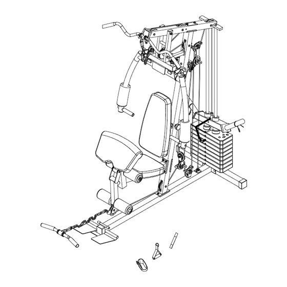
Page 29: Explosion Diagram
Explosion diagram... -
Page 30: Workout Area
Workout Area The free area must be at least 0.6m greater than the training area. This is a space where you can safely dismount, without obstruction, in case of an emergency. Where two pieces of equipment are positioned adjacent to each other the free area may be shared. Only one person should be within the training area when the equipment is in use... -
Page 31: Exercise Information
Exercise Information Before starting to exercise Before starting Tailor your exercise program according to your physical condition.if you have been inactive for several years,or are overweight, you must start slowly and increase your time on the equipment,a few minutes per workout increase is advisable. - Page 32 Exercise Information Muscle chart Aerobic Exercise Aerobic exercise improves the fitness of your lungs and heart - your body’s most important muscle. Aerobic exercise fitness is promoted by any activity that uses your large muscles (arms, legs or buttocks, for example). Weight Training Along with aerobic exercising which helps get rid of and keep off the excess fat that our bodies can store, weight training is an essential part of the routine process.
- Page 33 Exercise Information Warming up and Cooling down exercises Each workout should include the following three parts: 1. A warm up, consisting of 5 to 10 minutes of stretching and light exercise. A proper warm up increases your body temperature, heart rate and circulation in preparation for exercise. 2.
- Page 34 Exercise Information Calf / Achilles stretch With one leg in front of the other, reach forward and place your hands against a wall. Keep your back leg straight and your back foot flat on the floor. Bend your front leg, lean forward and move your hips toward the wall.
- Page 35 Exercise Information Using the home gym Important: When working out, do the following for each exercise: exhale while exerting/lifting and inhale while returning to starting position in a slow and controlled manner. Read all caution and warning stickers before using this equipment. ...
- Page 36 Exercise Information Seated Preacher Curl Developing the Biceps Select the desired weight. Adjust Preacher pad to desired height. Attach ‘Pull bar’ and chain to Lower pulley using Clip hooks. Position upper arms on Preacher pad. Grasp Pull bar with palms facing up. Curl bar upwards by pivoting from the elbow.
- Page 37 Exercise Information High Pulley Ab Crunch Developing the Abs / Core Select the desired weight. Attach ‘Lat bar’ to Upper pulley. Sit facing away from the equipment, locking your legs into Foam rolls for support. Grasp ‘Lat bar’ using a narrow grip with Lat bar behind your head.
-
Page 38: Parts List
Parts List...
Need help?
Do you have a question about the SCM-180 and is the answer not in the manual?
Questions and answers