Table of Contents
Advertisement
REV: XP18HPE_rev06192023
This manual provides information regarding the
operation and maintenance of these products. We
have made every effort to ensure the accuracy of the
information in this manual. We reserve the right to
change this product at any time without prior notice.
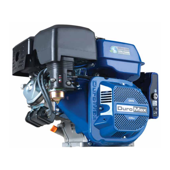
XP18HPE
S
E
R
V
I
C
Call our Customer Care Team Toll Free 8-5pm PST Mon-Fri
E
M
A
N
U A
5800 Ontario Mills Pkwy
Ontario, CA 91764 USA
www.duromaxpower.com
844-DUROMAX
L
Advertisement
Table of Contents

Subscribe to Our Youtube Channel
Related Manuals for DUROMAX XP18HPE


Summary of Contents for DUROMAX XP18HPE
- Page 1 XP18HPE REV: XP18HPE_rev06192023 5800 Ontario Mills Pkwy This manual provides information regarding the Ontario, CA 91764 USA operation and maintenance of these products. We www.duromaxpower.com have made every effort to ensure the accuracy of the Call our Customer Care Team Toll Free 8-5pm PST Mon-Fri information in this manual.
-
Page 3: Table Of Contents
CONTENTS Engine Components Engine Components ....................... 7 Maintenance and Care Maintenance Schedule ....................8 Break-In Period ....................... 9 High Altitude Operation ....................9 Changing the Carburetor Main Jet ................10 Checking the Oil ......................14 Changing the Oil ......................15 Changing the Air Filter .................... - Page 4 CONTENTS Common Engine Parts Common Engine Parts ....................36 Maintenance Log Maintenance Log......................41...
-
Page 7: Engine Components
ENGINE COMPONENTS 1. Air Filter 3. Fuel Tank 6. Recoil Handle 7. Starter Motor 8. Muffler 9. Engine Shaft 5. Key Switch Box 2. Carburetor 10. Oil Fill 4. Recoil Starter 11. Oil Drain Plug 1. Air Filter - A removable, cleanable, oiled, element that cleans the air going into the engine. 2. -
Page 8: Maintenance And Care
MAINTENANCE AND CARE Proper routine maintenance of your generator is essential for safe, economical, and trouble-free operation. It will also help reduce air pollution. WARNING: Improper maintenance, or failure to correct a problem before operation, can cause a malfunction in which you can be seriously injured or killed. Always follow the inspection, maintenance recommendations, and schedules in this instruction manual. -
Page 9: Break-In Period
Operation at altitudes below 3,000 feet (900 meters) with a modified carburetor may cause the engine to overheat and result in serious engine damage. Note: Jet kits available for purchase upon request, please contact us at 844-DUROMAX to set up your parts order. -
Page 10: Changing The Carburetor Main Jet
MAINTENANCE AND CARE (CONTINUED) Changing the Carburetor Main Jet Turn fuel valve OFF Turn the fuel valve OFF. Remove carburetor drain bolt Remove the outward angled bolt that is located on the bottom of the carburetor. Place funnel below drain port Place funnel with container to catch the gasoline under the drain port location and put drained gasoline in a gasoline safe container. - Page 11 Remove carburetor bowl Remove carburetor bowl from carburetor. Determine main jet location The carburetor jet is located inside the center metal tube of the carburetor. Remove main jet Remove the main jet with a flat head screwdriver. If necessary gently tap the carburetor to allow the jet and emulsion tube to fall out.
- Page 13 MAINTENANCE AND CARE (CONTINUED) Changing the Carburetor Main Jet (Continued) Reassemble engine Once the new jet is installed, reverse the above instructions to reassemble carburetor.
-
Page 14: Checking The Oil
(see “Adding Oil” portion of the “Maintenance” section). The oil will be visible in the oil fill spout when full. Be sure to replace the cap when finished checking oil. Model Number XP18HPE Engine Oil Capacity 37.2 fl. oz (1.1 L) -
Page 15: Changing The Oil
Changing the Oil CAUTION: Worn out or dirty oil does not cool the engine properly and can lead to catastrophic engine damage. In addition to regular oil changes, it is necessary to drain the oil from the crankcase if it has become contaminated with water or dirt. -
Page 16: Changing The Air Filter
Remove old filter element Remove the wing nut on top of the air filter element and slide filter element off center bolt. This filter is paper and is not reusable. Please call 1-844-DUROMAX to order a replacement filter for your engine. - Page 17 Replace new filter element Slide new filter element over center bolt, and replace wing nut. Tighten wing nut hand tight to keep filter in place. Replace filter cover Replace plastic air filter cover over the air filter base. Secure filter cover Fasten the air filter cover with the air filter cover wing nut and tighten about hand tight.
-
Page 18: Spark Plug Maintenance
MAINTENANCE AND CARE (CONTINUED) Spark Plug Maintenance The spark plug is important for proper engine operation. SPARK PLUG A good spark plug should be intact, free of deposits, and CONSULT MANUAL properly gapped. BEFORE REMOVING CAUTION: Improper maintenance may cause reduced fuel economy, misfires, trouble starting, or damage to the spark plug threads. - Page 19 Measure plug gap Measure the plug gap with a gauge. The gap should be 0.7-0.8 mm (0.028-0.031 in). Clean and re-gap If you are re-using the spark plug, use a wire brush to clean any dirt from around the spark plug base and then re-gap the spark plug.
-
Page 20: Emptying The Gas Tank
MAINTENANCE AND CARE (CONTINUED) Emptying the Gas Tank If you have been using gasoline in your engine, before storing your engine for extended periods of time you should drain your engine fuel tank of gasoline. CAUTION: Do not store fuel from one season to another. - Page 21 Turn fuel valve ON and drain Turn the fuel valve to “ON” and allow gasoline to drain into the container until the gas tank is empty. Shut fuel valve OFF Once the gasoline is fully drained, move the fuel valve back to the “OFF”...
-
Page 22: Storing The Engine For Same Day Use
MAINTENANCE AND CARE (CONTINUED) Storing the Engine for Same Day Use Run the engine Allow the engine to run for 3-5 minutes. Turn key switch to OFF Move the key switch to the “OFF” position to shut the engine off. Store engine After the engine shuts off and cools, then you can store the engine. -
Page 23: Storing The Engine For Use Within 30 Days
Storing the Engine for Use Within 30 Days Run the engine Allow the engine to run for 3-5 minutes. Shut fuel valve OFF and run dry Shut the fuel valve “OFF” and allow engine to run until it stalls out. Turn the key switch OFF Move the key switch to the “OFF”... -
Page 24: Storing The Engine For Longer Than 30 Days
MAINTENANCE AND CARE (CONTINUED) Storing the Engine for Longer Than 30 Days Run the engine Allow the engine to run for 3-5 minutes. Shut fuel valve OFF and run dry Shut the fuel valve “OFF” and allow engine to run until it stalls out. - Page 25 Remove spark plug Remove spark plug as shown in “Spark Plug Maintenance” on page 18. Add oil to cylinder Add 2 tablespoons of 10W-30 motor oil directly into the spark plug hole, and pull the recoil to lubricate cylinder. After lubricating cylinder reinstall the spark plug as shown in “Spark Plug Maintenance”...
-
Page 26: Check And Adjust Valve Clearance
MAINTENANCE AND CARE (CONTINUED) Check and Adjust Valve Clearance The engine intake and exhaust valve clearance should be checked and if necessary adjusted every 300 hours of use or 12 month period, whichever comes first. CAUTION: If the valve clearance isn’t maintained, this can cause the engine to run less efficiently and potentially cause engine damage. - Page 27 Remove spark plug Remove the spark plug with the provided spark plug wrench. Remove valve cover Remove all 4 bolts on the valve cover with an 8 mm socket wrench, then remove the valve cover. Set valves to top dead center Place screwdriver into spark plug hole to help determine the position of the piston, then slowly pull the recoil rope until the piston rises to the top position and both valves are closed...
- Page 29 MAINTENANCE AND CARE (CONTINUED) Check and Adjust Valve Clearance (Continued) Check exhaust valve clearance The exhaust valve is on the left side of the cylinder head. Slide a 0.008” (0.203 mm) feeler gauge in-between the valve head and rocker arm. If the feeler gauge is too loose, then tighten the rocker nut until the feeler fits firmly in the gap;...
-
Page 30: Specifications
SPECIFICATIONS Displacement 439cc Fuel Type ≥87 octane, ≤10% ethanol, unleaded gasoline Dry Weight 77 lbs Maximum Torque 27 ft. lb @ 2500 rpm Compression Ratio 8.5:1 Bore X Stroke 92 mm x 66 mm Engine Oil Capacity 37.2 oz. (1.1 L) Fuel Tank Capacity 1.7 gal. -
Page 31: Adjustment, Torque Values, And Timing Distribution
Adjustment, Torque, and Timing Specifications Adjustment Specification Spark Plug Clearance .027-.031 in. (0.7-0.8 mm) Spark Plug Type F6RTC (Torch), F6TC (Torch), BPR6ES (NGK), RN9YC (Champion), WR7DC (Bosch), W20EPR-U (Denso) Valve Clearance (Cold) Intake: .006 in ± .001 in. (0.15 mm ± 0.02 mm) Exhaust: .008 in ±... -
Page 32: Engine Diagrams
ENGINE DIAGRAMS Engine Diagrams 4X3/8-16 UNC-2B 71.5 71.5 4X5/16-24 UNF-2B 44.7 44.7 44.7 Ø146 -0.063 58.4 44.7 58.4... - Page 33 4X3/8-16 UNC-2B CRANKCASE COVER EDGE 71.5 71.5 4X5/16-24 UNF-2B 88.5 R12.7 +0.05 44.7 44.7 0.5 ~ 1.5 0.5 ~ 1.5 R0.1 ~ R0.35 C0.1 ~ 0.35 BOTH 60˚ SIDES 44.7 Ø146 -0.063 58.4 44.7 58.4 Ø25.4 -0.025 137.8 144.5 2XØ8 HOLE DEPTH 8...
-
Page 34: Wiring Diagram
ENGINE DIAGRAMS (CONTINUED) Wiring Diagram 1. Control Box 8. Oil Level Switch Black Yellow 2. Rectifier 9. Charging Coil Gray 3. Fuse 10. Ignition Coil 4. Circuit Breaker 11. Spark Plug White 5. Engine Switch 12. Starter Motor Bl/W Black/White 6. -
Page 35: Troubleshooting
TROUBLESHOOTING Mode Description Solution Engine switch is “OFF” Set engine switch to “ON” Fuel valve is “OFF” Turn fuel valve to “ON” Choke is open Close the choke Engine is out of fuel Add fuel Engine will not start Fuel is old or contaminated Change fuel Spark plug is dirty Clean spark plug... - Page 36 COMMON ENGINE PARTS Common Engine Parts 1. Oil Drain Bolt 11007-Z080110-00A0 2. Crankcase Assembly 11310-Z710210-0B00 3. Starting Motor Assembly 09100-Z190210-0000 4. Oil Protector 37050-Z010210-0000 5. Oil Fill Cap/Dipstick 15030-Z080130-Q500 6. Oil Seal 90682-Z310110-0000 7. Crankcase Cover 11411-Z100511-0BA0 8. Crankcase Cover Gasket 11001-Z100120-0000 9.
- Page 37 10. Valve Cover 12410-Z310110-0000 11. Breather Hose 17004-Z710210-0000 12. Valve Cover Gasket 12004-Z080110-0000 13. Cylinder Head Assembly 12140-Z710210-0BA9 14. Spark Plug 30010-Z010210-00A0 15. Cylinder Head Gasket 12131-Z710110-0000 16. Piston Rings 13200-Z710210-00A9 17. Piston 13111-Z710210-00A9 18. Pin Clip 13122-Z100110-00A0 19. Pin 13121-Z710110-00A0 20.
- Page 38 COMMON ENGINE PARTS (CONTINUED) Common Engine Parts (CONTINUED) 22. Camshaft Assembly 14200-Z190620-00A9 23. Ignition Coil Assembly 30400-Z190210-0000 24. Charge Coil Assembly 30140-Z160130-0000 25. Recoil Assembly 28100-Z710710BGBGE 28 29 26. Gasoline Fuel Line 90686-Z520110-00M1 27. Spacer/Cylinder Head Gasket 17002-Z100110-0000 28. Spacer Gasket 16003-Z100110-00A0 29.
- Page 39 32. Muffler Gasket 18101-Z080110-00A0 33. Manifold Assembly 18150-Z080210-00A0 34. Manifold Gasket 18001-Z190110-00A0 35. Muffler Assembly 18100-Z710510-0000 36. Throttle Return Spring 16012-Z080110-00A0 37. Governor Spring 16063-Z710210-0000 38. Key Switch Assembly 35000-Z160130-BG00 39. Fuel Filter 16652-Z010710-00A0 40. Fuel Tank Cap 16730-Z310310-00A0 41. Fuel Tank Assembly 16620-Z310410-BGA0 42.
- Page 40 COMMON ENGINE PARTS (CONTINUED) Common Engine Parts (CONTINUED) 44. Air Filter Element 17150-Z710110-0000 45. Air Filter Assembly 17100-Z710410-00A0...
- Page 41 MAINTENANCE LOG Maintenance Log As a best practice it’s recommended to keep a log of the engine hours and maintenance to ensure your engine is always operating to its full potential. Date Engine Hours Maintenance Performed...
- Page 42 MAINTENANCE LOG (CONTINUED) Date Engine Hours Maintenance Performed...
- Page 43 Date Engine Hours Maintenance Performed...
- Page 44 MAINTENANCE LOG (CONTINUED) Date Engine Hours Maintenance Performed...
- Page 45 Date Engine Hours Maintenance Performed...
- Page 46 MAINTENANCE LOG (CONTINUED) Date Engine Hours Maintenance Performed...
- Page 48 5800 Ontario Mills Parkway Ontario, CA 91764 United States 844-DUROMAX REV: XP18HPE_rev06192023...
Need help?
Do you have a question about the XP18HPE and is the answer not in the manual?
Questions and answers
how do you unbolt and remove the electric starter motor?