
Related Manuals for HM Digital CommPro Series


Summary of Contents for HM Digital CommPro Series
- Page 1 Installation & Service Guide XPRO-2500D XPRO-5000D XPRO-7500D XPRO-10000D XPRO-15000D Please read this manual carefully before attempting installation.
-
Page 2: Conditions For Operation
Please read this entire service guide prior to beginning installation. The CommPro Series commercial reverse osmosis system has been designed for quick and simple installation and maintenance. By carefully reading this instruction manual and following the operational guidelines you will insure a successful installation and reli- able operation. -
Page 3: Specifications
Specifications COMMPRO MODEL# XPRO-2500D XPRO-5000D XPRO-7500D XPRO-10000D XPRO-15000D System Design Treatment Configuration Single Pass Single Pass Single Pass Single Pass Single Pass Feed Water Quality TDS < 2,000 TDS < 2,000 TDS < 2,000 TDS < 2,000 TDS < 2,000 Recovery with Recycle* 35%-50% 35%-50%... -
Page 4: System Diagrams
System Diagrams DM-2 * INLINE DUAL TDS METER CHIP-V RO CONTROLLER; VERTICAL AFM-055 PANEL FLOWMETER C/W CONTROL PG-100-PC PANEL MOUNT GAUGE; 0-100 PSI S211YF02NPEG5 FEED SOLENOID; 3/4" N/C 120VAC PSEI012826E JG 3/4" CTS X 3/4" NPT MALE CONNECTOR, BLACK PFM-055 PANEL FLOWMETER 40L30N-1W * 4"X40"... - Page 5 12) 95880505 *** 5FBT05C4 - 5GPM; 1/2 HP 120V; PUMP AND MOTOR 95880710 **** 7FBT07C4 - 7GPM; 3/4 HP 120V; PUMP AND MOTOR 13) WPS-4-4MF-3-7-30-15 LOW PRESSURE SWITCH; 30-15 PSI 14) ACV15 PRODUCT CHECK VALVE; 1/2" FPT 15) S211YF02NPDG4 * FLUSH SOLENOID;...
-
Page 6: System Installation Instructions
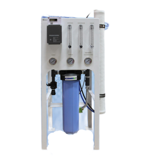
System Installation Instructions Feed Water Supply The 3/4" CTS push to connect fitting for the feed water supply is connected to the solenoid on the inlet side of the pre-filter. NOTE: Minimum line size for the feed line is 3/4" with a minimum pressure of 45 PSI not to exceed 85 PSI. - Page 7 Product check Concentrate valve Permeate System rear view Permeate (Product Water) Connection Locate the 1/2" O.D. push to connect fitting connected to the check valve located on the outlet (top) side of the permeate water flow meter. The permeate line should be connected to the storage tank by 1/2" O.D. poly tubing or other suitable material.
- Page 8 Tank Level Control All CommPro-Series systems are pre- wired for a tank level control (not included). Tank level control needs to be a normally closed switch (open connection in the tank full position shut the system down). 5' of wiring is included with the system. NOTE: Tank level control needs to only act as a dry contact.
- Page 9 Membrane Loading Instructions CommPro-Series systems are shipped without the membrane installed in the membrane pressure vessels. Membranes are left in their original packaging increasing the time frame the system can sit before installation. NOTE: Membranes must be loaded correctly. The brine seal on the membrane needs to be on the same side of the membrane housing as the feed water connection.
-
Page 10: Membrane Installation
Membrane Installation Brine seal Carefully remove membrane from the packaging. Note which end of the membrane that the brine seal is installed on as the membrane will need to be installed so that this is at the top of the vessel. With a smooth and constant motion, push the membrane into the housing. -
Page 11: System Start-Up
System Startup Divert permeate water to the drain temporarily. Fully open the concentrate adjustment valve by turning it counter-clockwise. Fully close the concentrate recycle adjustment valve by turning it clockwise. Turn on the feed water supply to the system and connect the power. The TANK FULL light should be flashing green indicating that the system is power on and in STANDBY. -
Page 12: Operation And Maintenance
Operation and Maintenance Pre-Filter Pressure Gauges 0 - 100 PSI The pre-filter in and pre-filter out gauges show the feed water pressure before and after the pre-filter when the system is running. If a pressure differential of 10-15 PSI is present it would indicate that the pre-filter requires changing. - Page 13 RO System Controller CommPro-Series systems include the CHIP system control. This operates all electrical components on the unit including: - Pump start delay - Low pressure protection - Tank level control - Pretreatment lockout - Auto flush (on deluxe models) System status is displayed on the front panel by a series of LED lights.
- Page 14 RO System Controller Electrical Connections NOTE: The system must be disconnected from the 120v power before opening the control box. It may be necessary to consult a qualified electrician before attempting repair or service. Pump/Motor 110-240 VAC Supply Power 110-240 VAC Inlet Valve 110-240 VAC Flush Valve...
-
Page 15: Troubleshooting
DM-2 Inline TDS Monitor SPECIFICATIONS TDS Range: 0-9990 ppm Resolution: 0-999: 1 ppm 1000-9990: 10 ppm (indicated by a blinking ‘x10’ icon - multiply the reading by10) Accuracy: +/-2% (of the reading) Conversion Factor: NaCl (avg. of 0.5) Factory Calibration: 342 ppm NaCl (digital calibration) Sensor Cable Length: 46”... -
Page 16: Conditions Of Warranty
CommPro Limited Warranty Water Industries warrants its CommPro-Series Reverse Osmosis system to be free from CommPro warrants its CommPro-Series Reverse Osmosis system to be free from defects in defects in materials and workmanship under normal use within the operating parameters materials and workmanship under normal use within the operating parameters listed below.
Need help?
Do you have a question about the CommPro Series and is the answer not in the manual?
Questions and answers