Advertisement
Advertisement
Table of Contents

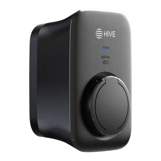
Summary of Contents for Hive EO Mini Pro 3
- Page 1 Hive EV Charging EO Mini Pro 3 Installation Guide...
-
Page 2: Table Of Contents
Contents Before you start Charger installation Software setup Smart Charging Randomised Delay PEN fault detection GSM – Hive SIM Customer registration Wiring connections Status light Hive support centre... -
Page 3: Before You Start
Before you start 1. Register with EO as an installer and complete the necessary induction modules. Failure to register with the EO academy may invalidate the customer’s warranty. 2. Ensure you have access to a mobile device that can connect to Wi-Fi, and appropriately sized cable glands, based on cable sizing. -
Page 4: Charger Installation
Installer Details label on the inside wall of the main housing (see image C) 2. Place the base of the EO Mini Pro 3 in the installation location and make sure the surface is flat and level. - Page 5 5. Attach the EO Mini Pro 3 base to the wall using the four screws provided. Make sure the charger is secure and flush against the wall. Use packing washers if necessary for a flush fit. 6. Strip and prepare the power cable and feed...
- Page 6 Wire designations for load management Connector Number CT Assignment CT Wiring Colour Function CT1B CT1A White The CT clamps supplied have a red and white wire attached to them. The CT for load management should be connected to CT1. Connect the white wire to position 2 and the red wire to position 1.
- Page 7 Make sure the lead is connected to the right-hand male connector of the rear case, as below: 10. With all cables securely connected, close the Mini Pro 3 cases together, making sure no internal cabling is trapped, and secure the housings together with the four hex bolts and washers.
-
Page 8: Software Setup
Software setup 1. Power up the charger. 2. You will see a hotspot with the name eo-xxxxxxxxxxxxxx - it may take a couple of minutes to appear. The hotspot expires after 10 minutes if no connection is made. You must power the charger down and back up again to reactivate the hotspot. - Page 9 8. Confirm charger settings. • Check and set the time in your location • Enter your installer details • Enter the charger current limit. This is set at 32A, but you may want to reduce this if site capacity is not adequate •...
- Page 10 CT Types Source: An external source of energy. Site: Boundary point into a property which will contain the charger usage within it. Load: An external load to the charger that does not contain the charger usage. Load Management Where a CT clamp is fitted you can set parameters for load management on the Load Balancing page.
-
Page 11: Smart Charging
Disable the toggle beneath Default Profile and set the Max Delay (beneath Randomised Delay) to 0. These will be overridden by the Hive app. If the charger will be used as a non-smart charger, without the Hive app: Set the Default Profile to suit the customer’s requirements. Otherwise, they will only be able to charge outside of the periods set by the factory. -
Page 12: Randomised Delay
Randomised Delay There is a risk of overloading the grid if lots of people start or stop charging their EV at the same time. To avoid this, all EV chargers now have a Randomised Delay feature. This means that there will be a random delay of up to 10 minutes when customers start or stop charging, which will help the grid stay balanced. -
Page 13: Pen Fault Detection
Physical EO Mini Pro 3 installation is now complete. The customer can now log in to the Hive App to complete setup of the charger. If the customer has not received a charger PIN from Hive then please follow the customer registration steps which follow. -
Page 14: Customer Registration
Customer registration The customer needs to be registered with Hive to receive the PIN that is required to add their EO Mini Pro 3 charger to the Hive App. You can complete this by: • Going to hivehome.com/ev-charging-retail or scanning the QR code on the Installer Details label •... - Page 15 IMPORTANT: The installer must select the RCD and earthing configuration by following the current local regulations and best practices. Where the EO Mini Pro 3 includes DC leakage protection a Type A RCD can be fitted at the supply, otherwise, a Type B RCD or equivalent should be used. EO recommends a 40A supply for a 32A charging station.
-
Page 16: Wiring Connections
PE= Protective Earth N = Neutral L1= Line/Phase 1 L2= Line/Phase 2 Status light The EO Mini Pro 3 has a status LED on the front face to show its status. When powering up LED colour State Notes Not illuminated... -
Page 17: Hive Support Centre
LED colour State Notes LED pulses blue Ready Ready to charge EO Mini Pro 3 is communicating with the vehicle and trying LED pulses green Cable is inserted to start a charging session LED solid green Charging A charging session has started successfully...


Need help?
Do you have a question about the EO Mini Pro 3 and is the answer not in the manual?
Questions and answers