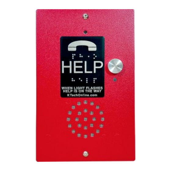
K-Tech ET401 Series Installation Manual
Hide thumbs
Also See for ET401 Series:
- Installation manual (2 pages) ,
- Quick programming manual (2 pages) ,
- Quick start manual
Advertisement
Quick Links
K-Tech International, Inc.
Torrington, CT USA
Record the phone number for the phone line. This is the number needed to call into the K-Tech phone.
Phone line must be an analog Central Office (CO), Plain Old Telephone Service line (POTS) or Analog Private Branch Exchange (PBX). All
special features such as call waiting and call forwarding should be disabled.
PHONE LINE: Must be a DTMF line with dial tone. Voltage between 24-51 volts. Amperage minimum - 30 mA.
No other equipment should be sharing the phone line, e.g. Fax, Modem, etc. (This is a safety code requirement in some areas. Check your
local code.)
Phone wire should be twisted shielded pair in the traveling cable and other places where possible. 18-22 AWG size recommended. Shielding
should be grounded at one end only.
TOOLS REQUIRED
Flat/Phillips head screwdriver
Drill for #8 sheet metal screw
1/4" nut driver (Fortress)
Wire cutter/stripper
Sentry & Liberator (Surface Mount):
1. Remove the phone's rear
enclosure.
2. Using the rear enclosure as a
template mark the mounting screw
hole locations.
3. Drill holes for the #8 screws
(included).
4. Mount the back cover to the
mounting surface.
NOTE: All phones should be grounded when mounted on a non-metal surface.
PROGRAM
SWITCH
BATTERY
1-800-993-9399
READ THIS BEFORE INSTALLING!
1. Hook up the phone line and connect the battery.
2. Check to make sure all the following are plugged in correctly: LED, speaker, button, microphone,
and battery. (Note: on OEM models, button wires are yellow. LED wires are red and black.)
3. Program and test the phone.
4. Remount dust cover to back of phone or mount phone to enclosure as required.
Fortress (Flush Mount):
1. Determine the location for the phone's
front plate on the car station panel or
other suitable surface.
2. Cut out an 8" high x 5.5" wide opening
to allow for the dust cover.
3. Position the unit in the hole and use
the face plate as a template to locate
the mounting screw holes.
4. Drill holes for the #8 screws
(included).
5. Remove the dust cover from the back
of the Fortress plate to program.
MIC
SPK
LED
SERIAL #
RING JUMPERS
PHONE LINE
BUTTON
Programming &
Installation Guide
WIRING & SET-UP
MOUNTING
1 – Voice Message #1 [Blank] (Automatic)
2 – Voice Message #2 [Serial number]
3 – Phone Directory [Blank]
4 – Auto shut off timer [05 minutes]
5 – Outgoing number of rings [4]
7 – Enter programming mode
8 – ID number [01]
9 – Security Code [ 1 2 3 4 ]
0 – Volume [5] (1 = softest; 7 = loudest)
# – Exit programming mode or shut-off
ET401 Series
Commander (COP Mount):
1. If studs are not present, use the plate
as a template to mark the stud
locations. Install studs.
2. Mount the OEM plate to the panel.
Make sure the cover is as tight to the
panel as possible to avoid feedback
and oscillations (squealing) between
the microphone and speaker.
3. Connect the remote push-button (not
included) to the appropriate wire going
to the phone board receptacle marked
BUTTON.
4. Install the included LED(s) or connect
the remote light to the appropriate wire
going to the phone board receptacle
marked LED.
Program Feature Number [Default Setting]
Memory Address 1, 2, 3, 4, 5 (phone number
must be at least one digit—max 30 digits)
Advertisement

Summary of Contents for K-Tech ET401 Series
- Page 1 Installation Guide READ THIS BEFORE INSTALLING! Record the phone number for the phone line. This is the number needed to call into the K-Tech phone. Phone line must be an analog Central Office (CO), Plain Old Telephone Service line (POTS) or Analog Private Branch Exchange (PBX). All ...
- Page 2 The battery should be replaced every 2 years, or after 30 hours of phone activation. BOK108 FCC Information — The K-Tech ET401 Series meets FCC 15 and 68 Original Sept. 2020 standards, IC and ETL approval. FCC Registration # ERC-USA-44557 WHEN CALLING TECH SUPPORT —...


Need help?
Do you have a question about the ET401 Series and is the answer not in the manual?
Questions and answers