
Related Manuals for Sun Seeker e-ECO TAD


Summary of Contents for Sun Seeker e-ECO TAD
- Page 1 TAD Supplemental Owner’s Manual Find us online at SunSeeker.Bike Revised 12/2020...
-
Page 2: Table Of Contents
Contents 1. Introduction ................2 2. Specifications ................. 2 3. Reference Views ..............3 4. Assembly Reference .............. 4 5. Assembly Guide ..............4-16 6. Read Before Riding ..............17 7. Pre-ride Checklist ..............18 8. Precautions & Warnings ............19 9. Motor ..................20 10. Display ..................21 11. King-Meter Display User Guide .......... -
Page 3: Introduction
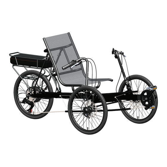
Introduction CONGRATULATIONS! Congratulations and welcome to the Sun Seeker Recumbent family! You have selected one of the most comfortable and advanced recumbents on the market. Please read this manual before riding your Sun Seeker Recumbent. In this manual you will find that we cover the basics for setting up and understanding your new recumbent. IMPORTANT: This manual is only a supplement to the main Recumbent Bicycle/Tricycle Owner’s Manual. Please read it before you take the first ride on your new recumbent bicycle/tricycle, and keep it for reference. NOTE: This manual is not intended as a comprehensive use, service, repair, or maintenance manual. Please see your dealer for all service, repairs or maintenance. Your dealer may also be able to refer you to classes, clinics or books on bicycle use, service, repair, or maintenance. e-ECO TAD Specifications Model: e-ECO TAD Style: Tadpole Electric Assist Trike Frame: Hi-Tensile Steel Fork: Hi-Tensile Steel Handlebar: Chromoly Steel Steering System: Direct Linkage Seat: 1-piece – Padded Base w/Steel Frame & Full Mesh Wheelbase: 37-1/2” (95cm) Overall Length: 70-1/2-78-3/4" (179-199cm) Width: 31” (79cm) Bottom Bracket Height: 13-3/4 -14-1/4" (35-36cm) Seat Height: 17-18” (42-45cm) Weight: 72 lbs. -
Page 4: Reference Views
TAD Reference Views Side View Top View... -
Page 5: Assembly Reference
TAD Assembly Reference e-DELTA Parts List ITEM DESCRIPTION Main Frame Assembly Crank Boom Assembly Right Front Wheel Assembly Left Front Wheel Assembly Rear Wheel Assembly Headset Seal Headset Bearing Headset Adjust Cone Headset Compression Ring Headset Spacer 10mm Headset Top Cap & Bolt Right Handlebar Assembly Left Handlebar Assembly Steering Linkage Assembly Seat Frame Assembly Bolt for Seat Frame (M8x90mm) Quick Release Seat Pin Seat Mesh (Not Pictured Above) Upper Seat Strut (16.0x150mm) Lower Seat Strut (12.7x380mm) Seat Strut Pin Extender Hardware Set 1 Set Seat Strut Hardware Set with Half-Moon Nylon Washers (Not Pictured Above) 1 Set Battery Carrier with Battery & Controller Rear Derailleur Chain & Chain Tube Assembly Pedals (9/16”) 1 Pair Seat Mount Bracket... -
Page 6: Assembly Guide
Assembly Guide Front Wheel and Handlebar Installation 1. Install #6 Headset Seal and #7 Headset Bearing (after lubricating bearing with grease) onto steer tube of the #3 Right Front Wheel Assembly. Insert steer tube into right-hand head tube. See Figure A. 2. Install #7 Bearing (after lubricating bearing with grease,) #6 Headset Seal, #8 Headset Adjust Cone, #9 Headset Compression Ring and two (2) #10 Headset Spacers onto the steer tube. See Figure B. 3. Install #12 Right Handlebar Assembly onto the remaining top portion of steer tube of #3 Right Front Wheel Assembly. Install #10 Headset Spacer and #11 Headset Top Cap and Bolt as shown in Figure B. 4. Install #13 Left Handlebar Assembly. Follow above procedure using the Left Handlebar Assembly. - Page 7 Assembly Guide Rear Wheel and Rear Derailleur Installation 1. Install #5 Rear Wheel Assembly into the rear frame drop outs. Be careful not to pinch wire on left side of axle. Tighten nuts securely. See Figure C. 2. Install #25 Rear Derailleur onto the rear frame derailleur tab. See Figure D. Tighten to 49 Nm (434 In. Lbs) Tighten to 8-10 Nm Tighten to 8-9 Nm (70-85 In. Lbs) (70-85 In. Lbs) Steering Linkage Installation 1. Install #14 Steering Linkage Assembly, using supplied hardware, into the inboard Steering Arm Tab holes (closest to rider.) See Figure E. Tighten to 8 Nm (69 In. Lbs)
- Page 8 Assembly Guide Setting Front Wheel Toe-In Angle 1. With the trike on the ground and wheels fixed in the straight ahead position, measure from the front of the left wheel centerline across to the front of the right wheel centerline. Record that measurement. See Figure F. 2. Repeat the above for the rear left wheel centerline across to the rear right wheel centerline. Record that measurement. The measurement should be the same or up to 3mm greater than the front centerline. (0mm to 3mm recommended) See Figure G. Hint for a simple measuring technique: Use a tape measure and hook one end on an inside spoke at the centerline of the left front wheel and measure to the opposing inside spoke on the front of the right hand wheel. Use the same technique at the rear. To adjust the toe in, loosen the Rod End Jam Nuts on the #14 Steering Linkage Assembly. See Figure H. Turn the Steering Linkage Assembly clockwise or counter clockwise. This will lengthen or shorten the rod since the rod ends are right hand threaded on one side and left hand threaded on the other. Tighten the Rod End Jam Nuts and recheck the wheel toe-in. Readjust if necessary.
- Page 9 Assembly Guide Crank Boom Installation 1. Connect 6-Pin cable with black connectors. Install #2 Crank Boom Assembly into the front of the frame. For now, insert midway and secure crank boom bolts. See Figure I. Do Not Lubricate Crank Boom 6-Pin Black Connector Tighten to 10-12 Nm (87-104 In. Lbs) 1. NOTE: Do not extend #2 Crank Boom Assembly past the safety line marked clearly on the boom. See Figure J. Do Not Extend Past This Safety Line 215 mm...
- Page 10 Assembly Guide Chain Tube Installation 1. Mount #26 Chain Tube Assembly with longer tube above the front axle and shorter tube below the axle. See Figure K.. 2. Also make sure the “Y” spring brackets are pointed toward the rear of the trike. Tighten to 3 Nm (26 In. Lbs)
- Page 11 Assembly Guide Chain Installation 1. Route chain into the #26 Chain Tube Assembly, then pull just enough chain out of #26 Chain Tube Assembly to go around chain ring. See Figure L. 2. Route the chain into the #26 Chain Tube Assembly, around the freewheel and through the rear derailleur. See Figure M. NOTE: C hain length is set for crank boom at its fully extended position. Chain and chain tubes may have to be shortened as necessary. Do not shorten until the rider has been fitted properly. NOTE: Adjust the upper rear chain tube to be far enough from the freewheel to not affect shifting.
- Page 12 Assembly Guide Battery Carrier Installation 1. Remove the pre-installed screws out of the frame, install the #24 Battery Carrier on the frame. See Figure O. Tighten to 3 Nm (26 In. Lbs) Tighten to 8 Nm (69 In. Lbs) Cable Routing, Brake 1. Connect the right/left brake cables to the right/left brake calipers. See Figure P, Q. Tighten to 6-8 Nm Tighten to 6-8 Nm (52-69 In. Lbs) (52-69 In. Lbs)
- Page 13 Assembly Guide Cable Routing, Rear Derailleur 1. Route the cable from right shift lever through the guides on the bottom of the frame, connect the cable on rear derailleur, with about 50mm cable reserved. Cut the excess cable, clamp on a ferrule. See Figure R. Tighten to 5-7 Nm (43-61 In. Lbs) Pedal Installation 1. Apply grease to the threads of the #27 Pedals. This will protect both the threads of the pedal and the crank arm over time. Use pedal washers where required. 2. Using your hands, thread the #27 Pedals (marked for L or R) into the respective left or right crank arms by turning them toward the front of the bike. 3. Once the threads catch, use your pedal wrench to finish tightening down the pedals. See Figure S. Tighten the pedals to a minimum of 260 in-lbs. of torque. Tighten to 29 Nm (260 In. Lbs)
- Page 14 al Connections Electrical Connections ectrical Connections Assembly Guide Assembly Guide Electrical Connections Electrical Connections...
- Page 15 Assembly Guide Seat Frame Assembly and Strut Installation 1. Install two #19 Upper Seat Struts and four(4) 1/2 moon washers with bolts nuts and washers to #15 Seat Frame with the provided hardware. See Figure U, V. 2. Insert two #20 Lower Seat Struts into #19 Upper Seat Struts and use two #21 Seat Strut Pins to secure the struts. 3. Install #28 Seat Mount Bracket using #16 M8x90mm Bolt through #15 Seat Frame tabs and secure with nut provided. See Figure V. 4. Install #28 Seat Mount Bracket onto #1 Main Frame and secure with #17 Quick Release Seat Pin. See Figure W. 5. I nstall #20 Lower Struts onto the rear frame mount tabs and secure with #22 Extender Hardware Set. Tighten to 6 Nm (52 In. Lbs)
- Page 16 Assembly Guide Crank Boom Adjustment Loosen the #2 Crank Boom Assembly clamp bolts and position the boom so that when seated, your knee is slightly bent when the forward foot is in the farthest pedaling position. See Figure X. Do Not Lubricate Crank Boom Do Not Extend Past This Safety Line Seat Adjustment The goal is for your seat (and therefore your weight) to be as far back as possible when your setup is complete. Adjust the seat angle by removing the #21 Seat Strut Pins and sliding the seat struts into a new position if necessary. Reinstall #21 Seat Strut Pins after adjustment. See Figure Y.
- Page 17 Assembly Guide Handlebar and Headset Adjustment 1. L oosen the clamp bolts that secure your #12 Right Handlebar Assembly to the steer tube then carefully loosen the #11 Headset Top Cap & Bolt. See Figure Z. 2. R otate the #12 Right Handlebar Assembly to the desired fit position then carefully retighten the #11 Headset Top Cap and Bolt only until play is removed from headset bearing assembly and the #3 Right Front Wheel Assembly still turns smoothly. Do not over tighten bearing assembly. 3. T ighten clamp bolts on #12 Right Handlebar Assembly until secure. Repeat adjustments for #13 Left Handlebar Assembly. 4. Recheck handlebar and headset adjustments after a short test ride. Tighten to 8-10 Nm (70-85 In. Lbs) WARNING: M ake sure that once you have made all your handlebar adjustments, you have sufficient clearance from your hands to your tires or wheels and that control cables are secured away from all moving parts. Failure to do so may result in loss of control resulting in a serious or fatal accident.
-
Page 18: Read Before Riding
PLEASE READ THIS BEFORE RIDING YOUR SUNSEEKER RECUMBENT This manual is intended to be read carefully so that you may enjoy your new recumbent and be an informed rider aware of the benefits as well as the warnings and safety issues in riding this recumbent. A recumbent trike is not a bicycle and this manual contains specific information and warnings that will let you enjoy your Sun Seeker Recumbent Trike in comfort and safety. Tricycling is a sport, and a mode of transportation. With it, comes the risk of an accident that could result in injury and even death. By riding this recumbent, you assume that risk. We want to give you as much information as possible to make you a safer rider. We cannot cover all contingencies, but we can make you more aware and informed. Be aware that: • M unicipal bicycle regulations also apply to recumbents. Most states and municipalities have bike regulations. It’s up to you to research those regulations and become informed. Your local dealer will be able to help you with this information. Since you will be sharing the road at times with other vehicles, a good rule to follow is “If you can’t do it with a bicycle, don’t do it with a recumbent”. • A recumbent trike’s widest point could be behind you at the rear wheels. If the front goes by an obstacle there is no guarantee that the rear wheels will also clear. When riding, you must give clearance to the edge of the road or sidewalk. Give extra room when passing near pedestrians and obstacles. Stay clear of potholes and be aware that you can lose control if any wheels should drop into a hole or catch an immobile object. Always ride defensively and watch out for the unexpected. This means everything from cars to kids, pets, and rough or hazardous road surfaces. Be prepared to avoid danger and ALWAYS WEAR A BICYCLE HELMET. We recommend buying your helmet from a local dealer that can fit and instruct you on the correct way to wear this helmet. Protecting your head is your primary safety responsibility. Always wear a CPSC, ANZI, ASTMS, or SNELL approved bicycle helmet. CPSC approval is the U.S. Federal Standard to which all helmets must comply. -
Page 19: Pre-Ride Checklist
PRE-RIDE CHECKLIST 1. C heck your tires for proper air pressure. Keep tire pressure between the minimum and maximum air pressure rating printed on the tire sidewall. Do not inflate over the maximum air pressure rating on the tire sidewall. 2. T est your brakes and make sure they stop the recumbent. If you have any doubts, do not ride, and see your dealer for service. 3. C heck that the handlebar is tight and that the ends are plugged. Check the saddle for tightness. 4. Move the recumbent forward and back. If you hear or feel any resistance, do not ride. If you feel that something is not right after performing your check, DO NOT RIDE. Take your recumbent to your local dealer for inspection. -
Page 20: Precautions & Warnings
PRECAUTIONS AND WARNINGS A recumbent trike does not handle like a bicycle. You cannot lean into a turn. Turns must be made more carefully and at a slower speed than a bicycle. All wheels must be on the ground at all times. Do not make sudden changes in direction that could unbalance the recumbent and cause an accident. When beginning to ride, stay at a slow speed. You must acclimate yourself to handling and turning this recumbent. If you feel insecure, slow down and proceed at a slower pace. With practice, you will become comfortable riding and stopping. The ability to climb hills on this electric recumbent will depend on the grade, rider weight, pedal input, and momentum. It is not advised to rely solely on the motor assist. Best results will come from a combination of motor and pedal assist. Tipping hazard. Turning sharply or turning at speeds above 5 mph can cause the recumbent to become unbalanced and tip over resulting in possible injury or death. For your safety, the maximum power-assisted speed of this recumbent is limited to 15 MPH. Keep both hands on the handlebar at all times. Riding with no hands can cause the recumbent to become unstable and tip over, resulting in possible injury or death. We recommend that you not ride at night or at times of reduced visibility. If you must ride at night or during reduced visibility, you must outfit your recumbent with a white front light and red rear light. Relying on reflectors is not adequate protection. Most municipalities require lights for night riding. Your local bicycle dealer can help you in selecting the right lighting system for your needs. INTENDED FOR RIDERS 13 YEARS OF AGE OR OLDER. MAXIMUM WEIGHT LIMIT FOR RIDER AND CARGO COMBINED IS 300 LBS. -
Page 21: Motor
Motor Brand: Bafang Model: RM G020.350.D Rear Motor Rated Voltage: 36V Rated Power: 350W > _ _ Efficiency (%): Noise Level: 50 dB Water Resistance Rating: IP65 Operating Temperature Range: -4°F ~ 113°F Weight: 9.0 LBS... -
Page 22: Display
DISPLAY Brand: King-Meter Model: Digital II left side display with removable throttle Rated Voltage: 36V DC Communication: UART Water Resistance Rating: IP65 Certificates: CE/ROHS Certificates: IP65 Operating Temperature Range: -4°F ~ 140°F * T hrottles are not legal in all municipalities. If it is not allowed in your area it can be easily removed by your dealer. See page 32. FEATURES: MPH/KM Current Speed, Average Speed, Maximum Speed, Odometer, Trip Odometer, Trip Time, Backlit Display, Walk Assist Mode, Battery Level Indicator, Changeable 1-5 Power Assist, Error Code Display. User Manual: For complete details on the operation and use of this display refer to the King-Meter User Manual included in the following section. For your safety, the maximum power assisted speed of this recumbent is limited to 15 MPH. -
Page 23: King-Meter Display User Guide
DISPLAY KING-METER USER GUIDE Digital II - LCD... - Page 24 DISPLAY Contents Preface ......................24 Appearance and Size ..................24 Material and Color ..................24 Function Summary and Button Definition ............25 Normal Display Area ..................25 Button Definition ..................26 Notes for Users....................26 Installation Instructions ..................27 Standard Operation ..................27 On/Off ......................27 Switch Speed Display Information .............. 27 Switch Riding Display Information .............. 27 Walk Assist Mode ..................28 Turning on Backlight ..................
-
Page 25: Preface
DISPLAY Preface To ensure best performance of your e-trike, please read this user manual before use. Here we provide details on hardware installation, setting and normal use of the Digital II-LCD display. Included are answers to your most frequently asked questions that will help speed up the troubleshooting process. Appearance and Size Material and Color Digital II-LCD housing material: Black polycarbonate. Working Temperature: [(-20) °C - (+60) °C] / [(-4) °F - (+140) °F] Display Size and Installation Size (Unit : mm) -
Page 26: Function Summary And Button Definition
DISPLAY Function Summary And Button Definition Digital II-LCD offers plenty of functions shown here, in order to meet many different needs. • Battery indicator • Speed display (Including current, maximum, and average speed display) • Distance display (Including trip distance, odometer) • Riding Time display • Lighting State display • Walking Mode display • Error Code display • Multiple Parameter setting Normal Display Area Chart 1 Digital II-LCD Normal Display Interface... -
Page 27: Button Definition
DISPLAY Button Definition The three buttons to the left of the Digital II-LCD display are as shown: (M) = MODE (+) = UP (-) = DOWN Notes For Users Be careful during installation, power down your e-trike before connecting or disconnecting the Digital II-LCD display. Avoid collisions that may damage the Digital II-LCD display. To prevent water damage, do not remove any sealing stickers. Lorem ipsum Lorem ipsum Lorem ipsum D o not tamper with the Digital II-LCD display's background Lorem ipsum parameters or factory software. S top using and contact your local bike shop immediately if display is faulty. -
Page 28: Installation Instructions
DISPLAY Installation Instructions Mount the display on the handlebar, adjust angle for best visibility and control. Connect the two plugs from display and controller, making sure that power is disconnected. Standard Operation On/Off Hold “MODE” to start display and supply power to the controller, e-trike will power on. Once powered on, press and hold “MODE”... -
Page 29: Walk Assist Mode
Walk Assist Mode DISPLAY Press and hold “DOWN” to activate Walk Assist Mode. Walk Assist Mode This Walk Assist setting will move the bike forward at a steady speed of 6km / 3.7mph Press and hold “DOWN” to activate Walk Assist Mode. to aid in moving trike when not riding. -
Page 30: Throttle Function (Removable)
DISPLAY Thumb Throttle (Removable)* The Digital II-LCD Display is equipped with connections for a separate throttle control. The maximum output voltage of this throttle signal line is 4.3V. *Throttles are not legal in all municipalities. If it is not allowed in your area it can be easily removed by your dealer. -
Page 31: User Setting
DISPLAY User Settings Hold "MODE" for several seconds to turn on display. Once powered on, hold the "UP" and "DOWN" for two seconds to enter settings. Brightness Of Backlight Using “UP” and “DOWN”, select backlight brightness from 1-3. Setting 1 is the lowest brightness, setting 3 is the highest brightness. Press “MODE” to confirm and switch to display unit setting. The default brightness setting of the Digital II-LCD display is 1. Brightness 1 Brightness 2 Brightness 3... -
Page 32: Frequently Asked Questions
DISPLAY Frequently Asked Questions Q: Why won’t my LED display power on? A: Check that the battery is charged, fully seated in the battery holder and powered on. A: Check the connections between the display wire harness and the controller. Q: My LED display has power, why don't I get assist? A: Check that the assist level on the LED display is at level 1 or above. Q: How do I correct an error code? A: Please bring your e-trike immediately to your local dealer for repairs. Warranty And Coverage Warranty Information King-Meter will be responsible for its limited warranty for a period of 24 months from the factory production date of the Digital II-LCD display, for any product that fails during this time due to manufacturing defects. The Following Circumstances Are Not Considered As Warranty Issues: • Opened, impacted or otherwise damaged display housings. • Broken connectors. • Scratches or other cosmetic damage. • Broken, pulled, or frayed wiring or other external wire damage. • Damage caused by natural disasters, fires or other forces beyond control. • Product that has exceeded the King-Meter warranty period. -
Page 33: Throttle Removal
DISPLAY Throttle Removal 1. Loosen and remove grip, brake lever and display. With display removed, open handlebar clamp and remove throttle assembly. Reinstall display, brake lever and grip. See figures AA, BB. Remove Thumb Throttle for e-TAD Circuit Block Diagram Diagram 1: Standard connector cable sequence table (display without throttle) Note: Most displays use a waterproof covering over exposed cables. Wire Sequence Wire Color Usage RED (VCC) Power(+) BLUE (K) -
Page 34: Software Version
DISPLAY Software Version This operating guide is for software version V1.3. Some versions of the e-trike LCD display may have slight differences. Appendix: Error Code Diagram 3: Standard error code display definition table. Code Display Definition Throttle not parked (stuck in high position) Throttle Fault Over-voltage protection Motor hall sensor fault Motor phase fault Controller temperature high protection Controller temperature sensor fault Current sensor fault Battery temperature protection Motor temperature protection Motor speed sensor fault KING-METER USER GUIDE... -
Page 35: Battery
BATTERY SPECIFICATIONS Brand: MPS Cell Type: Lithium Polymer Rated Capacity: 10.4 Ah Rated Energy: 374 Wh Rated Voltage: 36V DC Operating Temperature: -4°F~122°F -4°~122°F (-20~50°C) WARNING Charge Temperature: 32°F~113°F 32°~113°F (0~45°C) Do not leave key in battery lock during use. Key will fall Storage Temperature: -4°F~113°F -4°~113°F (-20~45°C) - Page 36 BATTERY Product Appearance Left View 1. Power Button 2. LED Indicator 3. Charging port Right View...
- Page 37 BATTERY Product Appearance Front View Left View 1. Power Button 2. LED Indicator 3. Charging port Right View 4. Power and Communication Port Standard Operation Product Appearance Power Button Left View Press and hold the power button for more than 1 second to power the battery on and off. The LED Indicator will sweep up the scale when the battery is turned on, down the scale when turned off. Product Appearance Battery Level Indicator Left View ...
- Page 38 BATTERY Product Appearance Auto Power Off Left View Battery will power off automatically if output current is less than 500mA for 24 hours. Charging Product Appearance Left View Charging port is located right beside the LED Indicator. Product Appearance Left View Open the charge port cap and plug the charging plug into charging port for charging. Product Appearance Close the charge port cap once charging is finished and charging plug is Left View 1. Power Button removed. 2. LED Indicator Product Appearance 3. Charging port Left View ...
- Page 39 BATTERY Charging Indicator Press the power button quickly to display current battery charge level on the battery LED indicator. Power Button Battery Level Indicator 1 Battery Level Indicator 2 Battery Level Indicator 3 Battery Level Indicator 4 & Warning Indicator Battery Level Indicator : Green Warning Indicator :...
- Page 40 BATTERY Battery Level Indicator Battery Level Indicator (1,2,3,4) Battery Level 75 - 100% 50 - 74% 25 - 49% 10 - 24% 0 - 9% Blinking No light Lighting Up : : : Charging Battery Level Indicator Battery Level Indicator (1,2,3,4) Battery Level 100% 75 - 99%...
- Page 41 Recovery Indicator When an error occurs, the battery level indicator will blink certain LEDs. You can Condition get the current battery condition according to the various patterns produced by the (1,2,3,4 ) battery LEDs. Remove the BATTERY charger from the If the Warning Indicator battery.
-
Page 42: Charger
CHARGER SPECIFICATIONS Brand: MPS Input Voltage: 100-240V AC ~ 2.0A (50/60 Hz) Output Voltage: 42.0V DC / 2.0A Brand: MPS Input Voltage: 100-240V AC~2.0A (50/60 Hz) CHARGING MODE Output Voltage: 42V DC ~2.0 A Red Light: Charging CHARGING MODE Green Light: Fully Charged Red Light: Charging Charge Time from Full Discharge: Approximately 6 hours Green Light: Fully Charged ChargeTime from Full Discharge: Approximately 5 hours... -
Page 43: Bluetooth App Manual
Bluetooth App Manual (Note: most images are from the Android App) 1. D ownload the mBike App from the ITunes App Store or Google Play Store. 2. Tap the "mBike" icon on your phone. 3. Once on the Home Screen, tap the "Settings" icon. Launch Dashboard Page to record your trip. Connect Bluetooth to enable this button. Bluetooth Lock function. Connect BT to enable button. Bluetooth Lock is activated and Dashboard button is disabled. Launch History Page. Launch Settings Page. Profile page is for optional basic data. User name "None" will be used unless filled in. Pair/Unpair for MPS battery pack. Shows the MAC address of the connected MPS battery pack. Shows the Battery Power level and Health status of the MPS battery. Tapping 4 consecutive times will show "Diagnostic". When "Diagnostic" is tapped it will launch the Diagnostic page. - Page 44 Bluetooth App Manual 4. O nce on the Settings screen, tap "Profile" and fill in your Profile information. 5. On the Settings screen, tap "Pair". 6. Once on the Select Device screen tap MPS then on the Settings screen you will see that battery is paired.
- Page 45 Bluetooth App Manual 7. O n the Settings screen tap "Version Info" 4 consecutive times for it show "Diagnostic" if it isn't already there . Tap "Diagnostic" to view real time battery information. There is a Pause, Resume function in the upper right hand corner of the screen. Shown below are the Android Diagnostic Tool Pages This page shows values like current, pack temperature, capacity and charging status. This page This page indicates any shows the pack errors voltage and the error values of all frequency. cells.
- Page 46 Bluetooth App Manual Shown below is the iOS Diagnostic Tool Page This block shows the voltage values of all cells. This block shows values like current, pack temperature, capacity and charging status. This block and the 5 items “HWFuseBlown”, “Charging OT(charging over time)”, “CFET”, “DFET”, “Cell” are indication of pack error occurrence.
- Page 47 Bluetooth App Manual 8. On the Home Screen tap the "Bike" button to to access Dashboard Page. 9. O n the Dashboard Page screen tap the "Stop" button to stop recording, save data and launch the Record Page. Time: Current time. Active Time: Accumulated time over 5km/h. Distance: Accumulated distance over 5km/h. System Temp: Current battery pack temperature. General share function button. Calories: Is a computation without the input of electric power.
- Page 48 Bluetooth App Manual 10. On the Home Screen tap the "Lock" when Bluetooth is connected. This will activate a warning when your bike is out of Bluetooth range. 11. On the Home Screen tap the "History" button to see your Activities (Trips) page. This page lists all your activities. Tapping any of the activities will open a record that will be shown on Record Page. See page 46. Tap the trash can button to Delete an activity record.
-
Page 49: Notes
Notes Sun Seeker P.O. Box 161859, Miami, FL 33116-1859 info@sunseeker.bike...
Need help?
Do you have a question about the e-ECO TAD and is the answer not in the manual?
Questions and answers
How do you adjust the front shifting linkage had to put new cable on and can’t get it to shift correct
To adjust the front shifting linkage on a Sun Seeker e-ECO TAD after replacing the cable:
1. Route the new cable from the right shift lever through the guides on the bottom of the frame.
2. Connect the cable to the rear derailleur, leaving about 50mm of cable as slack.
3. Cut off the excess cable and clamp on a ferrule.
4. Tighten the connection to 5–7 Nm (43–61 In. Lbs).
No specific front shifting linkage adjustment is mentioned beyond this.
This answer is automatically generated
How to change the rear tire on a recumbent etrike